")
")
| Issue |
Matériaux & Techniques
Volume 110, Number 3, 2022
|
|
|---|---|---|
| Article Number | 304 | |
| Number of page(s) | 12 | |
| Section | Mise en oeuvre des matériaux / Materials processing | |
| DOI | https://doi.org/10.1051/mattech/2022031 | |
| Published online | 16 September 2022 | |
Regular Article
Post-processing of additive manufactured parts: a numerical strategy applied in maxillary implantology
Parachèvement de pièces de fabrication additive : stratégie numérique appliquée en implantologie maxillaire
1
Pint, Personnalized Innovative Titanium, F-57000 Metz, France
2
Université de Lorraine, CNRS, Arts et Métiers, LEM3, F-57000 Metz, France
3
Université de Lorraine, CNRS, IJL, F-54000 Nancy, France
* e-mail: This email address is being protected from spambots. You need JavaScript enabled to view it.
Received:
15
December
2021
Accepted:
27
June
2022
Abstract
To obtain a functional part from additive manufacturing (AM) technologies, some surfaces require post-processing by machining. An approach is developed using additive manufacturing supports as a clamping device for the milling operation. A model combining an analytical approach to determine the cutting forces with a finite element model (FEM) to predict the dynamical response of the workpiece-supports system is proposed. The complex structure of the supports is homogenized with a simplified geometry with equivalent stiffness and mechanical properties. A case study from the biomedical field is proposed: the finishing operation of a custom-made maxillary reconstruction plate is simulated. A parametric study is proposed with: (1) two different lattice geometries used as support structures; (2) up and down milling; (3) different depths of cut.
Résumé
Pour obtenir une pièce fonctionnelle à partir des technologies de fabrication additive (AM), certaines surfaces doivent être parachevées par usinage. Une approche est proposée en conservant les supports de fabrication comme montage d’usinage. Un modèle combinant une approche analytique, pour déterminer les forces de coupe, et un modèle par éléments finis (FEM), pour prédire la réponse dynamique du système pièce-supports, est proposé. La structure complexe des supports est simplifiée en homogénéisant le volume avec une rigidité et des propriétés mécaniques équivalentes. Un cas d’étude issu du domaine biomédical est proposé : l’opération de finition d’une plaque de reconstruction maxillaire sur mesure est simulée. Une étude paramétrique est proposée avec : (1) deux géométries de lattices différentes utilisées comme structures de support ; (2) un fraisage en avalant et en opposition ; (3) différents engagements de coupe.
Key words: additive manufacturing / machining / analytical modeling / finite element modeling / biomedical
Mots clés : fabrication additive / usinage / modèle analytique / modélisation éléments finis / biomédicale
© P. Didier et al., 2022
 This is an Open Access article distributed under the terms of the Creative Commons Attribution License (https://creativecommons.org/licenses/by/4.0), which permits unrestricted use, distribution, and reproduction in any medium, provided the original work is properly cited.
1 Introduction
Metal additive manufacturing (AM) processes, and in particular laser powder bed fusion (LPBF) technology, provides solutions but required creativity to finalize the thought and desired part. It results in the development of “design for AM” techniques [1] and the corresponding value chain [2]. This process provides new opportunities but remains dependent on new constraints. 3D printing technologies generally provide an opportunity to rethink product design by taking advantage of the benefits of these new processes [3].
AM consists on to build an object, layer by layer from a 3D digital model. Near-net-shape geometry is then obtained, it remains dependent on complementary post-processing processes, which are essential for the post-fabrication finishing operations of the parts [4–6]. These finishing operations remain the main topic in the field of AM. For some surfaces in mechanical assemblies and connections, precise dimensions are required. Thus, a finishing operation by milling or grinding becomes necessary [7]. This aspect is not often taken into account today in the corresponding value chain (from powder supplying to finished part). However, several initiatives are being developed with hybrid machines where additive manufacturing and machining operations are performed in the same chamber [8].
Another aspect of the overall LPBF chain value concerns manufacturing support. In practice, the LPBF process does not allow absolute geometric freedom and additional support structures must be considered. However, the support structure is the side product of AM [9]. The primary objective of these sacrificial structures is to support and allow the realization of overhang surfaces that cannot support themselves, which have a critical angle of inclination relative to the manufacturing substrate [10]. Optimizing the positioning and orientation of the part on the production platform by taking into account this type of constraint is up-to-date [11]. The inclination angle of the surface also has a great influence on the roughness and can therefore also be taken into account in the step of placing the part on the production plate [12]. The supports can also have a thermal role. Indeed, the fusion of the layers by the laser leads to a fusion followed by rapid cooling. This results in a specific microstructure and residual stresses [13] which can induce deformations, cracks, or undesirable effects on the part [14], causing dimensional deviations. One way to limit these distortions is to size the supports and favor a more uniform heat dissipation by optimizing the hollow geometry of the supports [15]. Another limitation is linked to the non-productive costs of the supports, due to their significant manufacturing time. Thus, many studies on the optimization of these structures are proposed in the literature to respond to thermomechanical issues by considering the speed of manufacture. For example, Hussein et al. [16] suggest the use of lattice structures as supports. Depending on the geometry of the unit cell of the architectural network considered, the manufacturing speed can be considerably limited. Another way to improve the design of support structures is to adopt a topological optimization approach. Kuo et al. [17] propose a formulation making it possible to consider at the same time the quantity of material used, the manufacturing speed, and the final surface quality after supports removal. An interesting approach proposed by Langelaar [18] is to consider a drilling load for a topological optimization of the manufactured support. However, this loading is fixed, is not time-dependent, and can be applied for localized post-processing operations.
To improve the value chain of the LPBF process by taking into account the operation of finishing by milling, an approach is introduced in this study. It consists in considering the manufacturing supports, no longer simply as a support structure, but also as a custom-made clamping assembly for the machining operation. Thus, the supports are kept after manufacturing to do the post-processing of certain specific surfaces. This approach allows a gain of operations without additional positioning and tightening device (see Fig. 1). However, to achieve such an objective, several considerations must be taken into account and anticipated in the global digital chain of manufacturing. The first technical aspect to take into account is the appropriate positioning and orientation of the part on the production plate to make the surfaces considered accessible to the cutting tool. The second aspect concerns the geometry and the heterogeneity of rigidity of the overall fabricated structure, including the part and its supports. These factors are potentially unfavorable for the milling operation, due to the flexibility of the assembly. They can thus be the source of vibrations between the tool and the part [19], dimensional deviations, and poor surface quality [20].
The design of the manufactured part and the appropriate selection of the support structures must therefore integrate the loading of the finishing operations. The supports must have a mechanical strength suitable for this machining operation so as not to deteriorate the surface quality of the manufactured part. Therefore, a previous study [21] has shown that surface qualities and dimensional deviations depend on the support structures. The choice of supports must be considered as a key step in the associated digital chain of the additive manufacturing flux. This study proposes to enrich this value chain by considering a new step to design more efficient supports.
A hybrid analytical-numerical strategy to choose and validate the design of the support structures taking into account post-processing by milling is used. To obtain a fast and usable digital tool, a specific methodology previously was proposed in [22]. In this contribution, an evolution of the model allows taking into account a more complex machining trajectory. The methodology is then applied to a medical case study. The study focuses on the finishing stage by machining the abutment of a maxillary reconstruction plate. Traditionally deformed with clamps during surgery, obtaining a custom made plate saves time in the operating room and guarantees an optimized contact with the bone.
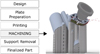 |
Fig. 1 Additive manufacturing flux. Machining of the functional surface using support as machining fixture. Illustration based on commercial support: Additive Designer – Additive Palletizing SLM Solution® (2018). |
2 Numerical strategy to model the dynamic behavior of milling operation
In this section, different solutions are combined to propose a numerical tool to determine the dynamic behavior of the part during machining and help in the design of AM supports. The operation of finish milling is specifically considered in this work. The global numerical strategy is recapped in Figure 2. The numerical strategy firstly involves the modeling of cutting forces when post-processing through an analytical oblique cutting modeling, which will be described in Section 2.1. Then, Section 2.2 describes the application of cutting forces on a finite element model. Section 2.3 explains the use of lattices as manufacturing supports and the homogenization procedure to be introduced in the FE model. Their mechanical properties can be adjusted by controlling the geometry of the lattice unit cell. In the developed numerical tool, a step of homogenization of these structures is also considered to optimize the computation time. The orientation of the part on the manufacturing plate also plays an important role. It directly conditions the height and the number of necessary manufacturing supports. Also, it has to be determined by making the machined surface accessible to the cutting tool. This choice will be developed in the presentation of the case study in part 3.
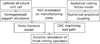 |
Fig. 2 Numerical strategy for predicting the dynamic behavior of LPBF parts during milling. |
2.1 Analytical modeling of cutting forces
Some assumptions were formulated to develop analytical-numerical modeling:
The model considers a post-processing operation on a near-net-shape part. The milling tool path is limited and the volume removed by the subtractive process is negligible compared with the part volume.
The model considers the rotating tool as rigid but the workpiece is mobile. Its stiffness is taken into account.
Several analytical modelizations describe the phenomena which occur during the action of cutting [23,24], using cutting edge force coefficients. These coefficients are elementary stress components that, integrated into the whole geometry of the tool, correspond to the pressures applied on the part. The present study uses previous work described by Moufki et al. [25] introducing a thermomechanical analytical approach based on the oblique cutting theory, adapted and experimentally validated to the particular case of peripheral milling on Ti–6Al–4V [26] and with equivalent conditions. This modeling allows determining the distribution of the forces along the cutting edge of the tool for helical milling tools.
The milling operation is analyzed in the global coordinate system (X, Y, Z) (see Fig. 3), where the cutting tool is represented by a cylinder of radius R, with a helix angle of αh and a number of edges between i and Nt . Only the inferior part of the tool engaged in the height ap . The variable thickness of the undeformed chip is noted t 1. During machining, the cutting edge rotates around the central axis (Z) of the tool with a rotation speed ω. The rotational positioning angle of the cutting edge portion being machined is noted by φ and corresponds to the parametric equation of the helix. This angle depends on the angle of rotation θ in the (XY) plane and the axial position Z. The positioning angle φ for a given edge i at time t, is then given by the equation:
 (1)
(1)
Depending on the radial depth of cut ae and the machining direction in up or down milling, the input angles φ in and output φ out of the edge element i in the material are given by:

The cutting edge is then decomposed into elementary elements of infinitesimal height dz , assumed rectilinear, and working in oblique cutting. The thermomechanical model of the oblique cut is applied [25]. This approach models shearing in the primary shear zone as well as the friction at the tool chip interface. The shearing of the material is described by a Johnson–Cook thermomechanical behavior law. The constitutive law allows considering the sensitivity to deformation, hardening, and thermal softening of the machined material. This analytical model makes it possible to calculate the specific pressures exerted by the tool per unit of quantity of material. These elementary stress components, the cutting edge force coefficients, are therefore valid for a cutting speed, a tool geometry, and given friction. For an elementary edge of one of the teeth of the tool, the specific cutting coefficients Kt , K r, and Ka respectively correspond to the tangential, radial, and axial directions, in the local coordinate system of the analytical model [22]. During the chip formation, additional shearing takes place in the tertiary deformation zone at the flank of the cutting edge; this mechanism is known as the plowing or rubbing process. The edge force coefficients Kte , Kre and Kae due to the rubbing forces are introduced as in the mechanistic approach. The cutting forces exerted on each edge entity are assumed to be proportional to the undeformed chip thickness t 1, making it possible to calculate the tangential elementary forces dFt , radial dF r, and axial dFa exerted on each element of height dz according to the equation:
 (4)
(4)
By integrating all the elementary force components, the total forces applied by the tool on the part are determined in the global coordinate system (X, Y, Z).
 (5)
(5)
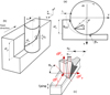 |
Fig. 3 Schematic view of the peripheral milling process on the (xy) plan (a) and definition of the cutting edge elements of thickness dz (b). Corresponding to an oblique operation (c) from [22]. |
2.2 Analytical-numerical coupling: applying cutting forces on a Finite Element mesh
To apply the cutting forces on a numerical FE model of the additive manufactured part, a numerical coupling is realized. This coupling is performed through an Abaqus subroutine (DLOAD) which allows the numerical application of pressure, defined by the cutting forces previously obtained by the analytical model. The milling is considered performed with a small depth of cut ae in comparison with the tool radius R and the volume of the workpiece. It is assumed that the cutting condition induces the removal of material with a negligible impact on the dynamics of the machined part. Thus, the numerical model does not take into account the change in the volume of the part and its volume is still constant. Therefore, no numerical elements have to be deleted, allowing significant savings in computing time.
Numerically, the rotation of the tool is discretized in angle increments, noted dθ, which correspond to the projection of the positioning angle φ in the (XY) plane (see Fig. 4). The number of increments per rotation of the tool must be large enough to describe the cut of the material and the action of each teeth. The increment of angle dθ allows to define the increment of time dt with respect to the speed of rotation of the tool:
 (6)
(6)
The increment of length dL, which corresponds to the maximum mesh size of the mesh on which the pressure will be applied, is thus defined.
 (7)
(7)
For each increment angle dθ, a tool engagement test in the material is first performed from the input angles θ in and output θ out, defined by the geometry of the problem and the geometry of the tool (see Eqs. (2) and (3)). θin and θ out correspond to φ in and φ out in the (XY) plane. This engagement test allows for determining the cutting edge engaged in the material. As a function of the axial engagement ap , the minimum height Z min and maximum height Z max of the engaged edge can be obtained at each instant t.
If the cutting edge is not engaged, the engagement test is declared null. Thus, depending on the position of the cutting edge during the formation of the chip, several elements of the mesh are activated. Depending on the operating conditions, it may even appear to take into account the engagement of several cutting edges. The cutting forces Fx, Fy, and Fz at each instant t are transcribed from the analytical model in a normal and tangential pressure in the global coordinate system (X, Y, Z). This pressure is variable as a function of time, of the number of activated elements, and of the force previously calculated. It should be noted that for a time t, the distribution of the pressure on the corresponding surface is homogeneous and does not take into account the variation of the chip thickness related to the helix angle (or z coordinate of the mesh).
An assumption is to consider the rotating tool to be perfectly rigid. Contrary to this, the machined workpiece is considered flexible and is deformed under the action of the cutting forces. The coupling subroutine accesses instantaneous workpiece displacement for each iteration. The spatial modification of its position influences the undeformed chip thickness t 1 of the edge in contact, and thus the applied cutting forces. Through the algorithm developed, the axial engagement ap can be updated in real-time, allowing an adjustment of the calculation of the cutting forces. The subroutine takes into account at each iteration, this modification during the integration of the specific cutting edge force coefficients for the determination of cutting forces. Thus, this real-time adjustment takes into account the tool–material interaction by considering the oscillation of the part requested. This application method does not require recalculating the cutting edge force coefficients at each iteration of the numerical simulation. All local effects of the cut are included in these coefficients from the applied analytical model, valid for a given material, tool geometry, and cutting speed. All other cutting parameters such as depth of cut can, therefore, be optimized to improve the dynamic behavior of the machined system.
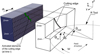 |
Fig. 4 According to the geometrical parameters of the milling operation (on the right), the hybrid analytical-numerical coupling in 3D activates elements corresponding to the cutting edge at time t (on the left) from [22]. |
2.3 Consideration of manufacturing supports: homogenization procedure of support structures
Previously, Hussein et al. [16] propose to use advanced lattice structures like support for additive manufacturing. Lattice structures are self-supporting, very thin, and permit easy removal of the loose powder trapped inside after the build is completed. These characteristics are well suited for support structures in the metallic AM process for saving material and energy while reducing time and cost. Moreover, the mechanical properties of various lattice structures are described in previous work [27].
A limit to the use of lattices is in the computation time associated with the dynamic behavior of such a complex structure. If the lattices are well known in the literature, they require significant means of calculation. Indeed, the very large number of small beams necessarily entails a very large mesh. A million elements are thus reached for only about thirty repetitions of the unit cell, at the origin of considerable computation time. It is in this context of saving time and optimizing the simulation that a homogenization procedure of lattice structures is considered (see Fig. 5), replacing the lattices support structure with a simplified geometry but with equivalent mechanical properties. A simple procedure of numerical homogenization by Finite Elements is applied. This method proposed by Steven [28] has been adapted to lattices [29]. For that, the stiffness matrix Cijkl is obtained in the elastic domain. It is a fourth-order matrix connecting the macroscopic strain tensor εkl to the macroscopic stress tensor σij in the Hooke law σij = Cijkl εkl . Due to the orthogonal symmetry, intrinsic to the group of cubic structures, the stiffness matrix C can be reduced from 81 to 9 constants. Six different boundary conditions are needed for the identification of constants. For each condition, one component of the strain tensor is equal to 1, while the other five are zero. For each strain condition, stress tensor results are obtained from the reaction forces on the appropriate faces. This constraint tensor directly provides the quantification of a line of the Cijkl matrix. From the constraint tensor data, the constants of the engineer are deduced. This homogenization procedure is applied to lattices with perfect geometry. It is noticeable that the manufactured structures will present differences due to certain topological deviations. These calculated equivalent mechanical properties need to be corrected by a calibration procedure based on experimental data and therefore a digital registration [22]. The calibration procedure considered the average manufactured truss diameters and the result of the procedure function of the type of structure is proposed in Table 1.
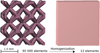 |
Fig. 5 Illustration of the homogenization of lattice structures to limit meshing with equivalent mechanical properties. |
Equivalent elastic properties in result of the homogenization procedure for the two types of lattices structures.
3 Application: side milling operation of a custom-made maxillary device abutment
Individualized implantology is an area of application particularly adapted to the LPBF process [30]. In the maxillofacial sphere, various pathologies and traumas may require a reconstruction stage using implantable medical devices, often made of Ti64 titanium alloy [31,32]. This is the case with some maxillary pathologies, where bone resorption is such important that the placement of endosseous dental implants is impossible. Several methods can therefore allow the rehabilitation of a functional maxillary denture. Among these techniques, surgeons can use osteosynthesis plates screwed to the maxillary bone by osteosynthesis screws. Several plates with an emerging abutment are assembled linked together on a dental bridge to carry out the functional reconstruction of the upper denture [33] (see Fig. 6a). Commercially, these devices are plate-shaped and are warped by the surgeon during the operation, causing a long intervention time to conform the geometry of the plate to the anatomy of the patient. The custom-made 3D printed devices allow a significant saving of surgery time (see Fig. 6b). If the surfaces in contact with the bone can have a geometric tolerance in agreement with the resolution allowed by the LPBF process and necessitate post-processing by polishing [4–6], the abutments of the plates form a precise assembly with the bridge and must have functional dimensions. Thus, they need finishing operations by machining. The positioning and orientation strategy of the part on the manufacturing plate must take into account several aspects. The area of supported surfaces must be minimized. In addition, the surface intended for contact with the bone must be spared as much as possible by the supports. Indeed, the manual removal of the supports leads to poor surface quality requiring polishing. We are interested in this study in the peripheral milling operation of the implant-abutment cylinder. It must therefore be accessible to the cutting tool during the machining operation. Consequently, the part is positioned on the manufacturing plate with an orientation of 45° relative to the manufacturing substrate. The accessibility of machining tools is increased by the use of specific printing plates [34]. The traditional 100 × 100 mm2 square plate is composed of various individual and detachable pawns, dedicated for each printed part clamped into the CNC machine (see Fig. 7). In this way, all machined surfaces are accessible for each printed piece.
The choice of part positioning makes it possible to define the geometry and the number of supports, and thus the implementation of the EF model. The geometry of the model is presented in Figure 8a. The manufacturing plate is not shown in the model and we consider an embedment at the base of the supports. The manufacturing supports are replaced by a full volume to which the homogenized material is assigned. Two structures well known in the literature were retained in this study: the octet-truss structure and the diagonal structure [35], both with beam diameters of 0.3 mm. The homogenization method used, developed in Section 2.3, makes it possible to define the elastic properties of these two types of homogenized material (see Tab. 1).
The model mesh presented an average size of the tetrahedral elements of 0.5 mm. The mesh is however refined at the level of the abutment cylinder which corresponds to the surface of application of the pressure modeling the cutting forces (see Sect. 2.2). This mesh size of 0.1 mm is defined according to the diameter of the tool (3 mm) with a radial engagement of 0.2 mm and the time increment chosen to discretize the rotation of the tool by 4.5 × 10⁻⁵ s. The pressure is variable in space and time and is implemented in Abaqus software by a load subroutine.
The peripheral milling operation is carried out using a 3 mm diameter tool, with 4 teeth, a lambda helix angle of 30°, and a cutting angle α of 8–10°. Other parameters are fixed: the radial engagement ae is 0.2 mm and the cutting speed Vc is 140 m/min, leading to a feed rate of 1600 mm/min. A machining pass, corresponding to a complete revolution of the 4 mm cylinder, will therefore have a duration of 1.06 s. 90 angle increments θ are sufficient to describe the cutting force signal for a tool revolution. Consequently, each numerical simulation includes 22 718 time increments of 4.5 µs to carry out the complete machining pass on the cylinder.
The objective of the study is to vary the type of support structure and the machining conditions to assess the impact of the parameters on the milling operation. Three parameters are evaluated: the type of support structure (diagonal or octet-truss), the milling strategy (machining in up-milling or down-milling), and the axial engagement ap (1 mm or 2 mm).
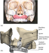 |
Fig. 6 (a) Maxillary reconstruction with four plates [33]; (b) Maxillary reconstruction with custom-made plates for LPBF additive manufacturing; (c) Custom-made plate positioned on AM plate for LPBF manufacturing. |
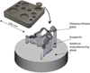 |
Fig. 7 Custom-made plate positioned on AM plate for LPBF manufacturing. Pawns are detachable for facilitating CNC milling. |
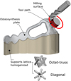 |
Fig. 8 Geometry of the finite element model for abutment milling operation and lattices associated. |
4 Dynamic simulation of abutment side milling operation
The stability of the machining operation is estimated by the displacement of the abutment cylinder relative to the cutting tool. For this, a change of coordinate system is made and the displacement of the central point of the upper surface of the abutment is observed in a rotating cylindrical coordinate system (r, θ, z) (see Fig. 9a). The radial and axial coordinates of the point (in the directions r and z) are determined depending on the position of the tool around the cylinder. These results can be observed on two scales: a global scale over the entire milling pass and a local scale over a tool rotation (see Fig. 9b). The global scale allows taking into account the effect of the global structure (composed of the part and the supports) with a different load at each time increment (point of application and direction and magnitude of cutting forces). The local scale makes it possible to specifically assess the impact of each tooth of the tool. A parametric study, varying type of structure, machining strategy, and axial depth of cut is proposed. Input parameters and output results are proposed in Table 2.
The two types of lattice structures are first compared, for an engagement of 1 mm and a strategy of machining in up milling (see Fig. 10). The axial or radial displacements are strongly reduced with the use of the more rigid structure (octet-truss). Also, for this structure, the signal is extremely stable and regular over the entire pass compared to the flexible structure (diagonal). Indeed, for the latter, the displacement is not the same depending on the machined area of the cylinder. This is especially the case during the first half of the milling pass. The radial displacement of the abutment reaches almost 100 µm, equivalent to half of the radial engagement. For the rigid structure, this maximum displacement is only 40 µm.
Then, the milling strategy parameter was observed (up-milling or down-milling), with a depth of cut of 1 mm and diagonal structure (see Fig. 11). This parameter modifies the distribution of the cutting forces and in particular the normal and tangent forces on the machined surface. The difference in terms of radial displacement is therefore not very obvious. The amplitudes differ little according to the machining strategy used. At the level of the axial displacement, it is slightly reduced with a down milling strategy, and the direction of the forces is reversed.
Finally, the parameter of the axial engagement ap is studied (see Fig. 12), conserving a diagonal structure and an up milling strategy. The height of the abutment cylinder is 2 mm. In one case, the axial engagement is 1 mm and only the upper half of the cylinder is machined. In the other case, the entire abutment is taken up in a milling pass. The influence of this parameter is not negligible and the radial displacement is reduced by approximately 20 µm when the axial engagement is minimized. However, the axial displacements are a little different.
The most influential parameter is the stiffness of the support structure used. The octet-truss structure ensures a more stable milling operation thanks to its much higher rigidity. However, the high stiffness difference is linked to a significant difference of relative density: 0.520 for the octet-truss structure against 0.257 for the Diagonal structure. Although less influential in this case study, the machining parameters still have a significant impact on the stability of the milling. They can also make it possible to modify the distribution of the forces and therefore to minimize displacements in certain directions.
The data obtained with the model (displacements and forces) make it possible to establish the minimum rigidity of the supports. The maximum rigidity of the supports must also be considered. These supports must not be too massive since they are intended to be removed from the part. A first simple approach would consist in considering a maximum relative density of structure for a given topology of structure. Gibson et al. [3], for example, reported on three types of mechanical behavior by classifying structures according to their relative density. This type of study gives indications on a relative density not to be exceeded, from which the structure has mechanical behavior close to a solid material.
The numerical strategy developed in this study stops at predicting the dynamic behavior of the machined system. There are, however, other approaches that make it possible to predict the surface qualities resulting from the milling operation with or without taking vibrations into account [36,37].
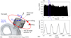 |
Fig. 9 (a) Abutment displacement evaluation in the cylindrical coordinate system; (b) Radial displacement at the global scale and at the local scale (at T1 position). |
Parametric study conditions and displacement results.
 |
Fig. 10 Radial and axial displacements of the machined cylinder on (a) global and (b) locale scale: comparison of the types of support structures (octet-truss and diagonal). |
 |
Fig. 11 Radial and axial displacements of the machined cylinder on (a) global and (b) local scale: comparison of milling strategy (up-milling or down-milling) with diagonal structure. |
 |
Fig. 12 Radial and axial displacements of the machined cylinder on (a) global and (b) local scale: comparison of milling strategy (1 mm or 2 mm) with diagonal structure. |
5 Conclusion
The objective of this work was to improve the additive manufacturing value chain by considering the stage of finishing by machining the manufactured parts. The idea developed considered the use of manufacturing supports as a custom-made clamping device for the machining operations of LPBF parts with an application on a medical case study. The focus was on the implant abutment, which needs to be tolerated to fit the dental bridge (see Fig. 6b), and therefore necessitate precision machining. The rest of the implant in contact with the bone and the gingival can be treated by polishing. A digital tool for evaluating and helping to choose the support structures and the machining conditions was developed.
The numerical strategy simulates the dynamic behavior of a machined part subjected to cutting forces. The modeling program developed allows a reduced computation time thanks to the hybrid analytical-numerical coupling. Implemented on manufacturing software, this numerical tool allows to improve the milling operation function of the outputs (surface quality criteria, time to cut). First of all, the manufacturing supports can be modulated and their rigidity controlled through the use of lattice structures. On the other hand, the parameters of the machining operation can vary the distribution and the amplitude of the cutting forces involved during milling. The orientation of the piece on the manufacturing plate also influences this stability. The displacements and the dynamic oscillations of the machined parts can therefore be minimized. Thus, the finishing operation by machining can be carried out under optimal conditions without vibration, to obtain a surface condition that meets dimensional expectations.
Nomenclature
ω : Angular velocity
αh : Helix angle
αn : Normal rake angle
R : Tool radius
ae : Radial depth of cut
ap : Axial depth of cut
ft : Feed rate per tooth
Nt : Number of teeth
φi : Angular position for the ith tooth
φen : Entrance angle
φex : Exit angle
θ : Angular position of the first cutting tooth (i = 1)
Δθ : Angular increment of the tool’s rotational movement
Δt : Time step used in the ABAQUS code (Δt = Δθ/ω)
Nbtr : Number of tool revolutions
x,y,z : Coordinate system
z : Axial position for a point cutting edge
dz : Thickness of an elementary disc corresponding to a cutting edge element at position z (width of cut machined by a cutting edge element)
z min, z max : Axial boundaries of the engaged part of the ith flute during cutting
ηs : Angle determining the shearing direction in the primary shear zone
ηc : Chip flow angle
φn : Normal shear angle
λ : Mean (or apparent) friction angle at the tool rake face
τh : Shear stress at the exit of the primary shear zone
σij : Cauchy stress tensor
εij : Strain tensor
Cijkl : Fourth order elasticity tensor
E 1,E 2,E 3 : Young’s moduli
G 12,G 23,G 31 : Shear moduli
ν 12,ν 23,ν 31 : Poisson’s ratios
f 1 : First natural frequency of the machined plate
dFt , dFr , dFa : Elementary cutting, thrust and lateral forces exerted by a chip element on the tool
dFx , dFy , dFz : Elementary forces exerted by the tool on the part in the global coordinate system (x, y, z)
Ktc , Krc , Kac : Cutting force coefficients
Kte , Kre , Kae : Edge force coefficients
Conflict of interest
Authors certify that there has no financial conflict of interest (e.g., consultancies, stock ownership, equity interest, patent/licensing arrangements, etc.) in connection with this article.
Acknowledgments
The authors wish to thank the European founding FEDER IMPLANT [38] for their valuable participation and support.
References
- M.K. Thompson, G. Moroni, T. Vaneker, et al., Design for additive manufacturing: Trends, opportunities, considerations, and constraints, CIRP Ann. – Manuf. Technol. 65(2), 737–760 (2016) [CrossRef] [Google Scholar]
- Y. Al-Meslemi, N. Anwer, L. Mathieu, Modeling key characteristics in the value chain of additive manufacturing, Proc. CIRP 70 , 90–95 (2018) [CrossRef] [Google Scholar]
- I. Gibson, D.W. Rosen, B. Stucker, Additive manufacturing technologies – Rapid prototyping to direct digital manufacturing, Springer, 2009 [Google Scholar]
- Z. Baicheng, L. Xiaohua, B. Jiaming, et al., Study of selective laser melting (SLM) Inconel 718 part surface improvement by electrochemical polishing, Materials & Design 116 , 531–537 (2017) [CrossRef] [Google Scholar]
- F. Salvatore, F. Grange, R. Kaminski, et al., Experimental and numerical study of media action during tribofinishing in the case of SLM titanium parts, Proc. CIRP 58 , 451–456 (2017) [CrossRef] [Google Scholar]
- K.C. Yung, T.Y. Xiao, H.S. Choy, et al., Laser polishing of additive manufactured CoCr alloy components with complex surface geometry, J. Mater. Process. Tech. 262 , 53–64 (2018) [CrossRef] [Google Scholar]
- E. Brinksmeier, G. Levy, D. Meyer, A.B. Spierings, Surface integrity of selective-laser-melted components, CIRP Ann. 59(1), 601–606 (2010) [CrossRef] [Google Scholar]
- P. Stavropoulos, P. Foteinopoulos, A. Papacharalampopoulos, et al., Addressing the challenges for the industrial application of additive manufacturing: Towards a hybrid solution, Int. J. Light. Mater. Manuf. 1(3), 157–168 (2018) [Google Scholar]
- K. Sanjay, Fabrication strategy. Additive manufacturing solutions, Springer, Cham, pp. 111–143, 2022 [Google Scholar]
- F. Calignano, Design optimization of supports for overhanging structures in aluminum and titanium alloys by selective laser melting, J. Mater. 64 , 203–213 (2014) [CrossRef] [Google Scholar]
- A.T. Gaynor, J.K. Guest, Topology optimization considering overhang constraints: Eliminating sacrificial support material in additive manufacturing through design, Struct. Multidiscip. Optim. 54(5), 1157–1172 (2016) [CrossRef] [Google Scholar]
- Z. Chen, X. Wu, D. Tomus, et al., Davies, surface roughness of selective laser melted Ti–6Al–4V alloy components, Addit. Manuf. 21 , 91–103 (2018) [Google Scholar]
- T. Mishurova, S. Cabeza, T. Thiede, et al., The influence of the support structure on residual stress and distortion in SLM Inconel 718 parts, Metall. Mater. Trans. A 49(7), 3038–3046 (2018) [CrossRef] [Google Scholar]
- P. Mercelis, J.P. Kruth, Residual stresses in selective laser sintering and selective laser melting, Rapid Prototyp. J. 12(5), 254–265 (2006) [CrossRef] [Google Scholar]
- M.X. Gan, C.H. Wong, Practical support structures for selective laser melting, J. Mater. Process. Technol. 238 , 474–484 (2016) [CrossRef] [Google Scholar]
- A. Hussein, L. Hao, C. Yan, et al., Advanced lattice support structures for metal additive manufacturing, J. Mater. Process. Technol. 213(7), 1019–1026 (2013) [CrossRef] [Google Scholar]
- Y.H. Kuo, C.C. Cheng, Y.S. Lin, et al., Support structure design in additive manufacturing based on topology optimization, Struct. Multidiscip. Optim. 57(1), 183–195 (2019) [Google Scholar]
- L. Matthijs, Integrated component-support topology optimization for additive manufacturing with post-machining, Rapid Prototyp. J. 25(2), 255–265 (2019) [CrossRef] [Google Scholar]
- S. Seguy, G. Dessein, L. Arnaud, Surface roughness variation of thin wall milling, related to modal interactions, Int. J. Mach. Tools Manuf. 48(3-4), 261–274 (2008) [Google Scholar]
- P. Michalik, J. Zajac, J.M. Hatala, et al., Monitoring surface roughness of thin-walled components from steel C45 machining down and up milling, Measurement 58 , 416–428 (2014) [CrossRef] [Google Scholar]
- P. Didier, G. Coz, G. Robin, et al., Consideration of SLM additive manufacturing supports on the stability of flexible structures in finish milling, J. Manuf. Process. 62 , 213–220 (2021) [CrossRef] [Google Scholar]
- P. Didier, G. Coz, G. Robin, et al., Consideration of additive manufacturing supports for post-processing by end milling: a hybrid analytical-numerical model and experimental validation, Prog. Addit. Manuf. 7(1), 15–27 (2022) [CrossRef] [Google Scholar]
- S. Jayaram, S.G. Kapoor, R.E. Devor, Estimation of the specific cutting pressures for mechanistic cutting force models, Int. J. Mach. Tools Manuf. 41(2), 265–281 (2001) [CrossRef] [Google Scholar]
- E. Budak, Y. Altintas, E. Armarego, Prediction of milling force coefficients from orthogonal cutting data, J. Manuf. Sci. Eng. 118(2), (1996) [Google Scholar]
- A. Moufki, D. Dudzinski, A. Molinari, et al., Thermoviscoplastic modelling of oblique cutting: forces and chip flow predictions, Int. J. Mech. Sci. 42(6), 1205–1232 (2000) [CrossRef] [Google Scholar]
- A. Moufki, D. Dudzinski, G. Le Coz, Prediction of cutting forces from an analytical model of oblique cutting, application to peripheral milling of Ti–6Al–4V alloy, Int. J. Adv. Manuf. Technol. 81(1), 615–626 (2015) [CrossRef] [Google Scholar]
- J. Favre, P. Lohmuller, B. Piotrowski, et al., A continuous crystallographic approach to generate cubic lattices and its effect on relative stiffness of architectured materials, Addit. Manuf. 21 , 359–368 (2018) [Google Scholar]
- G.P. Steven, Homogenization of multicomponent composite orthotropic materials using FEA, Commun. Numer. Meth. Eng. 13(7), 517–531 (1997) [CrossRef] [Google Scholar]
- S. Xu, J. Shen, S. Zhou, et al., Design of lattice structures with controlled anisotropy, Materials & Design 93 , 443–447 (2016) [CrossRef] [Google Scholar]
- W.S.W. Harun, et al., A review of powdered additive manufacturing techniques for Ti–6Al–4V biomedical applications, Powder Technol. 331 , 74–97 (2018) [CrossRef] [Google Scholar]
- K. Moiduddin, A. Al-Ahmari, M.A. Kindi, et al., Customized porous implants by additive manufacturing for zygomatic reconstruction, Biocybern. Biomed. Eng. 36(4), 719–730 (2016) [CrossRef] [Google Scholar]
- C. Cosma, N. Balc, D. Leordean, et al. Customized medical applications of selective laser melting manufacturing, Acad. J. Manuf. Eng. 13(1), (2015) [Google Scholar]
- G. Odin, G. Scortecci, F. Levratto, et al., Techniques avancées en implantologie basale, 11(3), 1–10 (2011) [Google Scholar]
- D. Paul, Solutions matériaux et géométriques pour la réalisation de dispositifs médicaux implantables sur-mesure en alliages de titane : application aux implants endo-osseux et supra-osseux obtenus par fabrication additive, Thèse, Université de Lorraine, 2019 [Google Scholar]
- V.S. Deshpande, N.A. Fleck, M.F. Ashby, Effective properties of the octet-truss lattice material, 49 , 1747–1769 (2001) [Google Scholar]
- M. Arizmendi, F.J. Campa, J. Fernandez, et al., Model for surface topography prediction in peripheral milling considering tool vibration, CIRP Ann. – Manuf. Technol. 58(1), 93–96 (2009) [CrossRef] [Google Scholar]
- P.G. Benardos, G.C. Vosniakos, Prediction of surface roughness in CNC face milling using neural networks and Taguchi’s design of experiments, Robot. Comput. Integr. Manuf. 18(5-6), 343–354 (2002) [CrossRef] [Google Scholar]
- IMPLANT : Programme Opérationnel FEDER Lorraine et Massif des Vosges de l’Université de LORRAINE (2014–2020), LO0019216 [Google Scholar]
Cite this article as: Paul Didier, Gael Le Coz, Boris Piotrowski, Pierre Bravetti, Pascal Laheurte, Abdelhadi Moufki, Post-processing of additive manufactured parts: a numerical strategy applied in maxillary implantology, Matériaux & Techniques 110, 304 (2022)
All Tables
Equivalent elastic properties in result of the homogenization procedure for the two types of lattices structures.
All Figures
|
Fig. 1 Additive manufacturing flux. Machining of the functional surface using support as machining fixture. Illustration based on commercial support: Additive Designer – Additive Palletizing SLM Solution® (2018). |
| In the text | |
|
Fig. 2 Numerical strategy for predicting the dynamic behavior of LPBF parts during milling. |
| In the text | |
|
Fig. 3 Schematic view of the peripheral milling process on the (xy) plan (a) and definition of the cutting edge elements of thickness dz (b). Corresponding to an oblique operation (c) from [22]. |
| In the text | |
|
Fig. 4 According to the geometrical parameters of the milling operation (on the right), the hybrid analytical-numerical coupling in 3D activates elements corresponding to the cutting edge at time t (on the left) from [22]. |
| In the text | |
|
Fig. 5 Illustration of the homogenization of lattice structures to limit meshing with equivalent mechanical properties. |
| In the text | |
|
Fig. 6 (a) Maxillary reconstruction with four plates [33]; (b) Maxillary reconstruction with custom-made plates for LPBF additive manufacturing; (c) Custom-made plate positioned on AM plate for LPBF manufacturing. |
| In the text | |
|
Fig. 7 Custom-made plate positioned on AM plate for LPBF manufacturing. Pawns are detachable for facilitating CNC milling. |
| In the text | |
|
Fig. 8 Geometry of the finite element model for abutment milling operation and lattices associated. |
| In the text | |
|
Fig. 9 (a) Abutment displacement evaluation in the cylindrical coordinate system; (b) Radial displacement at the global scale and at the local scale (at T1 position). |
| In the text | |
|
Fig. 10 Radial and axial displacements of the machined cylinder on (a) global and (b) locale scale: comparison of the types of support structures (octet-truss and diagonal). |
| In the text | |
|
Fig. 11 Radial and axial displacements of the machined cylinder on (a) global and (b) local scale: comparison of milling strategy (up-milling or down-milling) with diagonal structure. |
| In the text | |
|
Fig. 12 Radial and axial displacements of the machined cylinder on (a) global and (b) local scale: comparison of milling strategy (1 mm or 2 mm) with diagonal structure. |
| In the text | |
Current usage metrics show cumulative count of Article Views (full-text article views including HTML views, PDF and ePub downloads, according to the available data) and Abstracts Views on Vision4Press platform.
Data correspond to usage on the plateform after 2015. The current usage metrics is available 48-96 hours after online publication and is updated daily on week days.
Initial download of the metrics may take a while.