")
")
| Issue |
Matériaux & Techniques
Volume 114, Number 3, 2026
Special Issue on ‘Opportunities and Challenges of Hydrogen Use for Steelmaking Decarbonization’, edited by Ismael Matino, Valentina Colla and Akhilesh Swarnakar
|
|
|---|---|---|
| Article Number | 306 | |
| Number of page(s) | 14 | |
| DOI | https://doi.org/10.1051/mattech/2026003 | |
| Published online | 24 March 2026 | |
Original Article
Hydrogen plasma smelting reduction of Cr2O3/Chromite: challenges, insights, and initial results of direct and sustainable stainless-steel production★
1
K1-MET GmbH, Stahlstraße 14, A-4020 Linz, Austria
2
Technical University of Leoben, Franz-Josef-Straße 18, 8700 Leoben, Austria
3
KU Leuven, Kasteelpark Arenberg 44, 3001 Leuven, Belgium
* Corresponding author: This email address is being protected from spambots. You need JavaScript enabled to view it.
Received:
20
August
2025
Accepted:
29
December
2025
Abstract
By the end of 2050, the European Union aimed to decrease the carbon footprint (CO and CO2) considerably. It was targeted to achieve 80–95% less than the level of emissions in 1990. Hydrogen, as a clean reducing agent, can eliminate the carbon footprint from the steel industry considerably (up to 95%). However, some factors, such as the endothermic nature of H2 reduction and the thermodynamic resistance of some high-temperature mineral oxides against reduction by H2, hinder such achievement. Hydrogen plasma smelting reduction (HPSR), as an alternative promising method compared to H2 and conventional carbon-based reduction methods, has emerged both in the lab and on a pilot plant scale in the current years. The direct reduction of chromite ore by HPSR, containing both Cr2O3 and Fe2O3 (and FeO), enables single-step production of low-carbon ferrochromium or stainless steel. Chromium is the major alloyed element of stainless steel produced mainly through the primary metallurgy methods from chromite ore. The ore contains different mineral oxides in the spinel phases that complicate the reduction process. Therefore, the study of different factors on the reduction of pure Cr2O3 is the first step in evaluating the feasibility of ferrochromium production by HPSR. The plasma state provides enough reactivity and heat via the excited species of hydrogen to overcome the mentioned kinetic (THP = 5000-25000 K) and thermodynamic (ΔG°HP ≤ −1500 kJ/mol) obstacles. In this paper, the in-situ evaluation of reduction degree via hydrogen by optimizing gas flow rate, melting temperature, and activity on pure Cr2O3 and the mixture of it with selective acidic and basic fluxes in different crucibles (structural steel and magnesia-chromite refractory) was studied. Moreover, the required thermodynamic assessments for the experiment were conducted to clarify the feasibility of the reduction process.
Key words: carbon footprint / hydrogen plasma smelting reduction / Cr2O3 / low-carbon ferrochromium / in-situ evaluation / reduction degree
7th European Steel Technology and Application Days (ESTAD 2025), Physical (Verona, Italy), 6–9 October 2025.
© M. Jafarzadeh et al., 2026
 This is an Open Access article distributed under the terms of the Creative Commons Attribution License (https://creativecommons.org/licenses/by/4.0), which permits unrestricted use, distribution, and reproduction in any medium, provided the original work is properly cited.
1 Introduction
Chromium, as a dominant alloying element in stainless steels, plays a critical role in advanced and high-performance steels. In high-chromium steels, the amount of chromium ranges from 10.5 to 28 wt.%. FeCr is conventionally produced through the smelting process in a closed submerged arc furnace (SAF). The feedstock for this process comprises the combination of chromite ore and fluxes (sintered and pelletized) along with metallurgical coal or coke arranged in the form of a layered coke bed. This configuration provides a stable burden structure, consistent flow of feedstock, homogenous electrical conductivity, and effective gas removal from the porous structure without trapping. However, both preparation processes, including sintering, pelletizing, coke preparation, and chromite smelting process, are highly energy-intensive and result in an immense carbon footprint. Moreover, the beneficiation process of the chromite ore is a prerequisite to produce high-grade ore suitable for agglomerated feedstock, adding extra energy demand and subsequent environmental issues [1, 2].
Nowadays, the annual emitted carbon dioxide (CO2) associated with the conventional production methods of high-carbon ferrochromium (HCFeCr), such as SAF, is significant. It ranges from roughly 1.8 to 5.4 tons of CO2 per ton of HCFeCr [3]. Therefore, substantial waste of energy, noticeable CO2 emission, and introduction of undesired coke-based impurities (sulfur and phosphorous) to the HCFeCr are inherently related to such production processes. However, regarding the higher affinity of carbon for oxygen compared to metal oxides like chromium and iron, the formation of metal carbides from these oxides is thermodynamically feasible [4]. Subsequently, the carbon content in the produced FeCr is noticeable and typically varies from 4 to 10 wt.%. To modify the low-grade products, refining processes such as argon oxygen decarburization (AOD) and vacuum oxygen decarburization (VOD), involving decarburization and metallothermic reactions, are crucial. In addition to the smelting route for FeCr production, two other processes are known for recovering pure Cr2O3: electrodeposition and thermochemical reduction (i.e., aluminothermic and silicothermic) processes [5].
As formerly discussed, the current carbon-based reduction approaches not only increase the carbon footprint in the feedstock preparation and primary production process but also require further refining processes to produce cleaner products at the next step. This would lead to less efficiency and substantially increase the final price. Hence, the research efforts should prioritize clean, affordable, and environmentally friendly approaches to produce high-grade ferroalloys without intermediate refining processes. The priority in investigations is with introducing the effective and sustainable reducing agent to address the issues of low-grade FeCr (LCFeCr), reducing pollutant byproducts (CO2 emission), and improving the economic viability of the process (less preparation and refining process). In consequence, different strategies have aimed to stop further greenhouse gas (GHG) emissions and subsequent global warming caused by industry.
Hydrogen was introduced as a promising alternative due to its unique properties to address all the conventional carbon-driven challenges in the steel industry. However, since hydrogen is not as strong reducing agent as carbon, reduction process by molecular hydrogen always accompanied by endothermic energy changes, unlike C [6]. Production of water vapor as a major smelting byproduct in the hydrogen-based reduction processes, thereby enabling it as a promising alternative to conventional carbon-based reductants. However, the thermodynamic limitation of the application of H2 in metallurgical processes, such as lower affinity to oxygen and endothermal reactions, constrains its potential to reduce a wide range of mineral oxides. On the other hand, the high-temperature refractory characteristics of certain oxides, including Cr2O3, TiO2, MgO, etc., present extra challenges. The lower efficiency of the gas-solid interactions compared to gas-liquid and the high reaction temperatures required to melt down and decompose such refractory compounds hinder complete metal recovery. Therefore, increasing the reaction kinetics requires volumetric heat supply to the system besides hydrogen injection, leading to extreme energy consumption [7].
1.1 Overview of plasma
Plasma, recognized as a fourth state of matter, comprises free electric charges and partially ionized gases. In the plasma state, molecular hydrogen undergoes dissociation and excitation to form reactive species, including photons, free electrons, vibrationally and rotationally ionized molecular hydrogen (H*2), atomic hydrogen (H), and hydrogen ions (H+). The reduction potential (chemical reactivity) of these reactive species was reported in descending order as follows [8, 9]:
 (1)
(1)
From the thermodynamic perspective, the presence of highly reactive species in hydrogen plasma (HP) enables, theoretically, the reduction of any metal oxide (even those with refractory characteristics). This potential arises from the exceptionally high affinity of HP species for oxygen, surpassing all metals. Moreover, the intrinsic energy transport by excited species of HP can be directed and released on the reaction interface. In addition to the thermodynamic advantage of HP compared to conventional carbon reductants, it also offers superior kinetic features. Regarding lower Gibbs free energy of oxidation (higher affinity to oxygen), the activation energy barrier of the target metal oxide would be lower than the actual mode. As a result, the required energy and time to surpass the kinetic obstacles during the HP reduction should be much lower in comparison to carbon-based reductants, theoretically [10].
1.2 Thermal plasma
Thermal plasma, a subdivision of the plasma’s different modes, is generated by applying direct or alternating current (DC/AC) between a cathode and an anode at an absolute pressure of > 0.1 atm. The temperature range for dissociation and ionization of various plasma gases is demonstrated in Figure 1. According to thermodynamic calculations, thermal plasma is typically obtained in the range of 5000°C to 25000°C, depending on the gas type. In consequence, despite the high achievable temperatures, the concentration of completely ionized species in thermal plasma is often very low. However, power supply for dissociation and available gas type (and its concentration) directly impact the efficiency of the reactive species generation. It is important to note that the lifetime of ions is extremely low (∼ 4 ms for H+). Hence, plasma always contains a mixture of different forms of excited species, enabling us to take advantage of them in the extended period [7]. By applying thermal plasma to the reaction interface, the localized heat source progresses the smelting process without supplying the external heat. On the other hand, thermal plasma is divided into transferred and non-transferred arcs based on the configuration of the electrodes. In a DC transferred arc plasma, the arc is established between the cathode (electrode) and the anode (workpiece). The anode drop (voltage drop) in the workpiece due to high electron flux to the anode and subsequent electron-ion recombination reactions at the reaction interface (workpiece surface) is the main reason for increasing temperature at the surface of the workpiece. As a result, this category of thermal plasma is a suitable candidate for utilization in high-temperature applications such as smelting reduction processes [11].
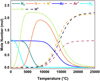 |
Fig. 1 Dissociation and ionization of plasma-forming gases over the temperature at 100 kPa (FactSageTM 8.3, Database FactPS). |
1.3 HPSR process
The HPSR process holds significant potential for the rapid reduction of various low-grade, ultra-fine mineral ores. DC transferred-arc thermal plasma is employed to produce highly reactive hydrogen species. Hence, thermodynamic and kinetic barriers of the reduction process could be surpassed by creating extremely high localized temperature in the arc attachment zone (AAZ) of the anode. Furthermore, the simplicity of plasma generation technology and affordability of maintenance (compared to other plasma torches) make the process scalable for industrial applications. The advantage of producing high-grade clean steel and ferroalloys in a single-step operation positions HPSR as a promising candidate for the next generation of carbon-free reactors. This method partakes of conceptual resemblance to the electric reduction process (ELRED) developed by ASEA, which employed a water-cooled hollow graphite electrode (HGE) to introduce fine feedstock directly to the plasma arc zone [12].
The schematic representation of the laboratory-scale HPSR reactor and the operational process via hydrogen plasma arc ignition are demonstrated in Figures 2a and 2b. As shown in Figure 2a, the reactor was equipped with HGE, cooled via a water-cooled electrode holder, for a simultaneous charge of feedstock and a mixture of plasma-forming gases into the AAZ. As shown, the detection of quality and characterization of the excited species and vaporized dust during the reduction process is feasible through the window, allowing for optical emission spectroscopy (OES). Furthermore, the opposite window provides access for dust collection and enables online monitoring and detection of the filtered (dust-free), dehumidified exhaust gas by mass spectrometry (MS). The ignition of the plasma arc between the HGE (cathode) and the steel pin (anode) was formed by applying an electric potential. Notably, initial direct contact between electrodes is required in the inert atmosphere (filled with argon) to ensure stable ignition at the beginning of the pre-melting step. Following ignition, the plasma was formed and was sustained under the continuous gas injection into the system. To monitor the operation parameters during the smelting process, the reactor is equipped with a pressure gauge and a visual inspection camera. As shown in Figure 2b, by melting down the reaction pin and batch feedstock, the electrical conductivity is maintained through the molten bath rather than the steel pin at the ignition step. According to Figure 2c, the key steps of the HPSR mechanism at the gas-slag reaction interface include (i) transport of the reactive species of hydrogen plasma to the reaction interface; (ii) transport of the oxygen from molten slag to the reaction interface; (iii) reduction of metal oxides and oxidation of plasma species (both excited and vibrationally excited molecular hydrogen); (iv) desorption and removal of the water vapor (dominant byproduct) from the system along with dust and gas flow from the system (also reverse reaction (oxidation) is possible due to the water vapor dissociation (to H, O, OH−) in exposure to the hot core of the plasma); and (v) precipitation and separation of the recovered metal due to the density difference at the slag-metal interface [7, 10].
Liquid-gas interaction in the reaction interface is fundamental to the rapid reduction process features of the HPSR method. However, the exceptionally high melting point of pure Cr2O3 ( = 2435 °C) and its refractory nature (being a thermodynamically stable oxide) cause considerable challenges for achieving a sustaining molten slag (consistent liquid phase) throughout the crucible. In practice, consistent melt formation is limited to the AAZ in the case of lack of proper control on the heat loss through the reactor refractory lining system, cooling system, exhaust gas flow, etc. [14]. Therefore, different strategies to suppress this issue can be employed, such as heat balancing calculations in the lining system of the reactor to improve isolation, increasing power supply (heat input), and adjusting gas composition and flow rate. In addition to the structural factors, designing a suitable eutectic system in the slag to lower the overall melting point and increase the solubility of the chromite into the slag is also crucial factor for thermal efficiency and process consistency.
 |
Fig. 2 The reduction process of metal oxides via the HPSR process, including (a) reactor showcase, (b) first ignition of thermal plasma arc, and (c) reduction process [13]. |
1.4 The role of fluxing
In addition to the operational modifications, mixing target oxide (Cr2O3) with fluxes to lower the overall melting point of the input material, thereby promoting sustained melt to achieve higher kinetics and degree of reduction, is critical. In the design of synthetic mixtures for slag composed of binary or multi-component systems, the target metal oxide determines the selection of final fluxes. While fluxes usually lower the activity of the target oxide in the slag, choosing the ideal fluxes should be based on maintaining the activity high enough to proceed with complete reduction. In addition, the flux components must exhibit higher thermodynamic stability than the target oxide to hinder interference in the reduction process. The stability of fluxes should be maintained against electro-reduction in exposure to the hot zone of the plasma arc (due to electric field in AAZ). This factor can be assessed by standard decomposition potential calculated for different fluxes under the electrical field at elevated temperatures (close to the plasma operation temperature). As shown in Figure 3, the relative stability of the common fluxes ranked from the least to the most stable oxides:
 (2)
(2)
Based on this decomposition order, lime (CaO), magnesia (MgO), alumina (Al2O3), and silica (SiO2) serve as potential candidates for the consequent thermodynamic evaluations. However, thermal decomposition of silica to silicon monoxide (SiO) and subsequent evaporation of it from the slag due to the exposure to extremely high temperatures (≥ 2000 °C) under thermal plasma should also be considered. Such calculations should focus on lowering the melting point of slag, decreasing the chance of forming potential stable spinels, increasing the activity, and adjusting the basicity to improve the solubility of the target oxide in the system [15]. On the other hand, thermodynamic calculations reveal a significant decrease in viscosity of nearly all forms of the fluxes over 1500°C (Fig. 4). Moreover, in case of pure silica presence or rising acidity of the slag (B2 = 0.6), viscosity increases drastically. As shown, enhancing the content of alkaline oxides to adjust the basicity of the system could directly lower the viscosity and increase the solubility of the system by changing slag composition. Therefore, such low melting point slags can be assessed with accompanying Cr2O3 in terms of achieving the highest activity and lowest melting point.
As shown in Figure 3, the decomposition potential of the common fluxes at the operating temperature of plasma (∼ 2500 °C) tends to the lower value. Hence, the vulnerability of the slag creators for decomposition under electrical field in the elevated temperatures would increase and approach the similarly low value. However, since Cr2O3 is the least stable oxide (except FeO) compared to fluxes, the process is not sensitive to the thermal decomposition of the fluxes during the reduction. While this facilitates the decision about selecting limitless types of fluxes, the chemical affinity of the Cr2O3 to form stable (high melting point) spinels with fluxes restricts the type and content of utilizing various mixtures. This factor will significantly affect the activity of Cr2O3 and the chemical properties of the produced slag directly. Thus, from a thermodynamic standpoint, it is nearly impossible to improve all relevant slag parameters simply by mixing Cr2O3 with a single flux despite achieving a low-temperature molten bath. For instance, the melting temperature of the single fluxes and the specific conductance of them near the melting point (liquid phase) are demonstrated in Figure 5. As shown, while the melting point of some of the fluxes, such as silica and fluorspar, provides ideal conditions in the pre-melting step, the low electrical conductivity of most of them hinders the formation of the stable arc in thermal plasma. Therefore, the plasma efficiency to melt down the present feedstock considerably drops since the refractory nature and electrically resistant characteristic of the Cr2O3 deteriorate such a situation, too. Therefore, at the constant current (I), higher voltage (V) and, consequently, higher power input (U) are required to generate plasma in the case of components with electrical resistance. However, despite fluxes, FeO indicates an ideal dissolver for Cr2O3 and plasma stabilizer due to the achievable low melting point and high electric conductivity. FeO would also not show negative side effects on the chemical parameters of the slag since it would be reduced in the next step prior to Cr2O3. It could also not interfere in the further reduction progress, as no stable spinel will be formed. However, maintaining fluidity for the reduction step is only achievable via a combination of other fluxes due to the preferential reducibility of FeO in advance of Cr2O3. Hence, adjusting basicity (via changing B2 =  , B3 =
  , or B4 =
  ) to take advantage of the consistent low-temperature mixture while providing the highest activity to the target oxide can offer a solution to the reduction step.
As previously discussed, the strong affinity of Cr2O3 for some of the fluxing oxides in the synthetic mixtures leads to producing high-temperature stable spinels, affecting the reduction efficiency negatively. The free energy of the reaction of Cr2O3 with different synthetic fluxes is illustrated in Figure 6. As displayed, FeO exhibits the highest Gibbs free energy of reaction with Cr2O3, representing the metastable behavior of the produced solid solution. On the other hand, in terms of the presence of FeO in complex systems, it would sacrifice itself by forming more stable spinels by flux. As shown, further control over spinel formation can be applied through adjusting basicity in the system (i.e., CaO and SiO2), too. Therefore, the study of basicity in complex systems facilitates future investigations into the chromite ore.
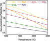 |
Fig. 3 Decomposition potential (volts) of the metal oxides in a pure state close to the melting point [15]. |
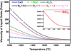 |
Fig. 4 Viscosity of molten slag (single mineral oxides and complex systems) vs. temperature (FactSageTM 8.3, Database FactPS & FToxid). |
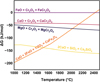 |
Fig. 6 Gibbs free energy of the formation for the spinels in the binary systems (FactSageTM 8.3, Database FToxid). |
1.5 Aim of the study
The aim of this study is to investigate the feasibility of producing ferrochromium via HPSR process to replace the conventional (SAF) route. As discussed, the HPSR process can show several advantages over SAF route, including the elimination of CO2 emissions from steel industry, the removal of several steps of integrated route in primary production, and a faster process due to thermodynamic and kinetic superiority. In addition to characteristics of thermal plasma and the properties of different plasma generating gases, the thermodynamic evaluation of the fluxes in the slag helped understand principles in adjusting these parameters for Cr2O3 reduction in the HPSR reactor. To achieve this goal and clarify the feasibility of underlying factors, various experiments on both pure Cr2O3 and synthetic chromite have been carried out to analyze the production of metallic Cr and ferrochromium. These experiments were designed to understand not only the behavior of the Cr2O3 on direct exposure to HP but also the impact of slag chemistry on the reduction efficiency with the addition single and complex fluxes (changing the basicity change). In addition, the effect of molten Fe underneath the slag on process efficiency and minimizing the Cr loss from the system was studied. The following experiments detail the operating parameters, feed composition, and results obtained.
2 Material and methods
2.1 Thermal plasma equipment
The experiment setup consisted of HGE serving as a cathode and a graphite plate acting as an anode positioned beneath the steel crucible. The generation of DC transferred-arc plasma with different compositions and ratios of gas injection for both the pre-melting and reduction steps was enabled through this configuration. The refractory materials were lined with the inner reactor chambers to minimize the heat loss and seal the reaction atmosphere during the reduction process (Fig. 2a). The hollow graphite electrode (HGE) was mounted on a hollow steel threaded rod to enable charging and gas injection to the arc reaction zone. In the pre-melting step, a gas mixture of 50% Ar and 50% N2 was introduced to the system at the total flow rate of 5 L/min. Next, during the reduction step, the same flow rate was adjusted with the gas mixture of 60% Ar and 40% H2. The arc ignition was initiated in the absence of gas flow by inertizing the reactor with Ar and establishing the direct contact between HGE and the central steel pin welded onto the crucible. Once the arc was initiated, the operation was maintained with the gas flow of the pre-melting step in the adjustable stable arc distance. As melting and the subsequent reduction progressed, the feedstock volume in the crucible changed due to phase transformation (solid to liquid) and oxygen loss during the pre-melting and reduction, respectively. Moreover, rising the melting temperature of the slag with the reduction progress due to the increasing flux ratio in the system is another reason for destabilizing the plasma arc. These factors are the main reasons for voltage rise as the arc distance changes by melting down of the feedstock in the different steps of reduction. Furthermore, synthetic slag formation with extremely high-temperature components can lead to consecutive voltage fluctuation. Such refractory components can solidify instantly since the thermal plasma arc can only surpass the melting point slightly. Such a phenomenon can be intensified by a high ratio of Cr2O3 in the generated slag. On the other hand, steel pins and HGE are consumable and erodible. Thus, electrode wear and pin removal both increase the arc length in which the voltage drop should be compensated via balancing the arc distance. The average power input for the whole process ranged between 4.5 and 6.5 kW, with a maximum of 6.9 kW. Current and voltage varied in the range of 90–110 A and 50–70 V, respectively. The arc ignition began with 100% power settled via a silicon-controlled rectifier (SCR) controller setting using a thyristor, with operational power maintained in the approximate range of 75% to 85% of the maximum power throughout the experiment. To apply this modification, the real-time control of the arc characteristics was possible through manual regulation of power level and cathode position. The entire process was monitored virtually through the viewport. In addition, the dust-free exhaust gas was continuously analyzed by MS after passing through a series of filters (ceramic filter, water, and silica gel). As a result, in situ compositional monitoring of the off-gas stream during both pre-melting and reduction stages was possible.
2.2 Feedstock and crucible
The raw material used in the experiments consisted of high-purity fine powders of Cr2O3 (particle size: 0.5–2.5 μm, purity ≥ 99.9%), CaO (particle size ≤ 10 μm, purity ≥ 99.9%), SiO2 (particle size ≤ 30 μm, purity ≥ 99.9%), high-grade iron ore, and pure iron chips. Detailed specifications for the chemical composition of iron ore are provided in Table 1. The experiments were conducted in batch mode using a low-alloy, high-strength structural steel crucible (grade ST52), opting to minimize slag contamination by interactions with the inner wall of the crucible and subsequent introduction of unwanted metal oxides into the slag during the smelting process. However, for the samples containing iron chip additives, a magnesia-chromite refractory crucible was employed due to its superior chemical and thermal stability against dissolution into the formed slag. This selection was inevitable, considering the similar melting point of the iron chips and previously used low-alloy steel crucible. Otherwise, such similarity could lead to shifting plasma direction from the center and melting down the crucible wall. It is due to the similar electrical conductivity of both the crucible and the feedstock and the plasma arc's preference to sustain itself at the least resistive path from the anode. The chemical composition of the refractory crucible is illustrated in Table 1. To enhance the thermal conductivity, improve reaction kinetics, and lower the dust formation during the process, the fine powder mixtures were cold pressed into the rectangular cubic bars under uniaxial pressure of 6 bar. As a result, uniform and rapid transition of the feedstock into the molten phase in a short exposure period to the thermal plasma would be achieved. The produced press bars’ dimensions were designed with a width and length of 10 × 20 mm, with the varying height for each bar tailored to ensure optimal fit within the crucible geometry. All raw materials were pre-dried in the laboratory oven at 300°C for 24 hours prior to mechanical mixing and pressing.
Chemical composition of iron ore and magnesia-chromite refractory crucible.
2.3 Experiment process
A total of 100 g of feedstock was charged in each experimental run. The specific composition of mixed samples positioned on top of iron chips (in case of addition) is detailed in Table 2. The initial trial involved only pure particles of ultrafine Cr2O3 serving as a reference sample. In the subsequent experiments, the effect of adding iron chips, iron ore (iron oxide), CaO, and a basic flux mixture (CaO + SiO2) to the Cr2O3 matrix was studied. As previously described, the plasma-forming gas mixture of Ar and N2 was injected during the pre-melting step to stabilize the plasma arc (by Ar) and maximize the generated heat content (regarding the higher ionization and dissociation energy of N2 than Ar) within the reaction zone, respectively [16]. This step was sustained for 20 minutes, during which a fully molten bath was achieved. The plasma gas mixture was then switched to Ar-H2 to start and maintain the reduction step for an additional 60 minutes. After this period, the plasma arc was extinguished by shutting down the power supply, and the sample was cooled down in a neutral Ar atmosphere to avoid oxidation. The operation parameters were kept similar with all other experiments to maintain comparability and reproducibility of each trial with later studies. In addition to input gas, the exhaust gas was primarily composed of water vapor, the major clean byproduct of the hydrogen reduction process. Moreover, trace amounts of CO and CO2 were detected, likely resulting from erosion of HGE during the smelting process. This phenomenon is due to the slag slushing to the electrode tip and heterogenous shift reactions between HGE and the dissociated oxygen from the produced water vapor. The use of iron chips instead of iron ore in the selected tests was intended to provide the molten bath to facilitate dissolving and mixing slag components, obtaining homogenous slag. The impact of the presence or absence of molten metal underneath the slag layer on the reduction progress is demonstrated in Figure 7.
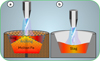 |
Fig. 7 Schematic reduction procedure with the HPSR process in (a) presence (refractory crucible) and (b) lack (steel crucible) of iron chips in the feedstock. |
Chemical composition of the feedstock for each trial.
3 Results
3.1 Hydrogen evolution and reduction degree
The hydrogen plasma smelting reduction of Cr2O3 in the generated plasma-liquid interface proceeds in the following sequential steps:
Dissolution of the fine Cr2O3 particles into the slag during the pre-melting step,
Dissociation of Cr2O3 to its comprising ions,
Dissociation of molecular hydrogen to excited species,
Transferring and introducing electrons and reactive hydrogen species into the reaction zone in the boundary layer,
Adsorption and chemical reaction of the HP species, oxygen, and dissociated Cr2O3 in the reaction interface,
Reduction of chromium ion by excited species of hydrogen into the yield of metallic chromium and water vapor, respectively, and
Transferring of produced water vapor form the through the reaction interface in the gas phase, as described in equations (3)–(6).
 (3)
(3)
 (4)
(4)
 (5)
(5)
 (6)
(6)
The metal oxide dissociation and subsequent chemical reaction of it with the excited species of the hydrogen are formulated in equations (7)–(9)
 (7)
(7)
 (8)
(8)
 (9)
(9)
Multiple experiments have been carried out so far, and various aspects of in situ and post-process analysis were considered for the evaluation of reactants and products under ongoing investigation. One of the most critical indicators for the progress of the operation is the reduction degree (RD), primarily attained from MS data analysis collected from the produced exhaust gas during the reduction phase. This factor provides the opportunity for a comparative assessment among experiments since most operating parameters remain constant. In addition to the exhaust gas analysis, RD is calculated by other measurable variables, such as loss on ignition (LOI), weight change of the graphite electrode, weight change of the feedstock, cycle duration, molar masses, and standard or ideal gas volume (STP). In consequence, the cumulative total reduction degree could be achieved by calculating RD for each reducing agent (H2, C, and CO) separately. The amount of the consumed hydrogen (produced water vapor) represents the degree of reduced Cr2O3 exclusively via hydrogen plasma. This value can be estimated through the difference between the total injected hydrogen volume and the unreacted volume of hydrogen detected in the exhaust gas stream. The relationship between water vapor and total hydrogen in each time cycle during the reduction is expressed in equation (10):
 (10)
(10)
Where  refers to the absolute volume of produced water vapor during the measuring cycle. Additionally,
  and
and  represent volumetric flow rates of hydrogen in the inlet gas supply and off-gas stream, respectively. The absolute value for
  and
and  would be determined by multiplying them by the operation time (tcyc). To determine the molar quantity of produced water vapor, calculated
  is converted to moles by dividing it by the standard molar gas volume of an ideal gas at STP, which equals 22.414 L/mol, as demonstrated in equation (11):
 (11)
(11)
This molar value is directly corresponding to the molarity of oxygen (reduced form Cr2O3) inside the water since only one oxygen atom is available in each water molecule. To compute the mass of reduced oxygen, the result will be multiplied by the molar mass of oxygen in water (16 g/mol), yielding  , the actual mass of reduced oxygen during the reduction process. Finally,
  , representing the reduction degree contributed to hydrogen, determined by dividing the mass of oxygen removed by the total theoretical oxygen content with the charged Cr2O3, is demonstrated in equation (12):
 (12)
(12)
The output hydrogen content in the exhaust gas for each experiment during the smelting process is illustrated in Figure 8. According to equations (3) to (9), the reduction degree by hydrogen ( ) for pure Cr2O3 (H 001) for a flow rate of 5 L/min under Ar–40% H2 plasma gas composition was calculated to be 17%. However, the addition of a considerable amount of iron chips to the feedstock slightly increased the
  to 25% (H 002) due to improved thermal conductivity by the underneath molten bath. Furthermore, the production of FeCr instead of pure Cr is preferable. Dissolving reduced Cr within molten Fe protects it against evaporation due to overheating by HP. On the other hand, the activity of the produced Cr in the system decreased in consequence of lowering its concentration in the molten Fe. However, this enhancement is considered with the onset of metal formation and subsequent slag repulsion from the AAZ, which limits further reduction (Figs. 7a and 9b). Moreover, CaO addition (H 004) to lower the melting point of the slag and to achieve consistent melt during the reduction was suppressed by complex spinel formation. Therefore,
  value decreased to 13% due to the stable behavior of the formed spinel inhibiting Cr2O3 and later reduction. On the other hand, simultaneous addition of CaO and SiO2 to adjust basicity (B2) to 1.67 with an overall flux content of 40% in the feedstock drops the
  value to 9%. There are two reasons to address this issue, including low activity of the Cr2O3 due to high amount of flux in the slag and the possibility of more stable spinel formation. Moreover, the efficiency of SiO2 in the slag will be reduced due to breaking most of its network at high basicity. Finally, operating the experiment with the mixture of Cr2O3 with iron ore (H 005) promoted melt homogeneity and melting behavior in the pre-melting stage, leading to enhanced hydrogen utilization in the reduction stage. However, regarding the concurrent reduction of both oxides, it is hard to quantify Cr reduction.
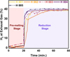 |
Fig. 8 H2 content in exhaust gas recorded by MS. |
 |
Fig. 9 The cross-section of products after the smelting process for the samples containing (a) pure Cr2O3, (b) iron chips and feedstocks, and (c) feedstock with iron ore as an additive. |
3.2 Metallization
The total metallization degree (Mtotal%) through the EPMA (for porous metal samples) and ICP-OES (for solid metal products without porosities) results are calculatable. Such results can be achieved by relatively simple approach of dividing the mass of total metalized products (mCr° + mFe°) by the total metal content in the input feedstock ( ). It should be noted that the content of Fe chips is excluded from the calculations. The detailed description of this value is given in equation (13) [17]:
 (13)
(13)
Individual metallization of each reducing metal oxide has been also reported in former studies. Similar to the approach mentioned for the total metallization degree, it is possible to obtain metallization degree of each individual component (MCr/Fe%) in the produced FeCr by considering the mass of each dissolved metal ( ) in the metal product. The detailed description is expressed in equation (14) [18]:
 (14)
(14)
It has been reported that due to the requirement for multi-step reduction of chromite slags (Fe2O3 → Fe3O4 → FeO → Fe and Cr2O3 → CrO → Cr) to attain a metallic product, there is no linear relation between metallization degree and chromite reduction [17]. Furthermore, it is likely that a considerable portion of the recovered metals are trapped in the high-temperature and viscose slag and vaporize during smelting process. Therefore, the calculated volume for reduction degree does not in correspond the metal content (%Mtotal) obtained after reduction. However, metallization degree provides valuable information on the efficiency of the process due to the comparison of the final obtainable solid metal.
The comparison of reduction degree ( ) achieved by HP and metallization degree (%Mtotal & %MCr/Fe) of each process is depicted in Figure 10. As shown, there is not any metal product in H 001 despite the fact the 17% of
  was calculated for that. However, a significant recovery of Cr (%Mtotal = 36.9%) in terms of adding Fe chips to the system (H 002) was obtained. The result is consistent with the higher value of
  in H 002 compared to H 001. While the metallization degree is increased in the sample containing iron oxide in the slag composition (H 003) a major part of metal produced belongs to Fe. According to the thermodynamic priority of the full reduction of the iron oxide over Cr2O3, only 3.6% of Cr from the input feed is metallized. The addition of high amount of lime to the slag (H 004) did not facilitate the reduction process despite the fact that it was predicted to lower the melting temperature in binary phase with Cr2O3. This can be explained by the formation of stable complex spinels like CaCr2O4 and the very high melting point of CaO (2572 °C), which challenges both the reduction progress and the formation of a stable molten slag. As a result, only a negligible amount of Cr (0.59%) was metallized, which contradicts the reduction degree. Such situation takes place by the bonding of partially reduced metal oxides (Cr2O3 → CrO) with CaO, which prevents further recovery of Cr2+ to Cr0. The detrimental impact of CaO in suppressing the recovery of metal oxides was only dedicated to the Cr2O3. Such a fact was revealed through the results obtained from H 005, indicating high Fe metallization despite limited recovery of Cr. On the other hand, the presence of SiO2 in the system trapped most CaO in its semi-crystalline lattice along with the beneficial effect of molten Fe underneath the slag, providing the better recovery of Cr2O3. In contrast to lower calculated reduction degree in H 005 compared to H 004, metallization of the Cr in the current experiment is higher due to the full reduction process (Cr2O3 → CrO → Cr). In consequence, the comparison of results discloses negative impact of synthesizing Cr2O3 with conventional fluxes despite the beneficial effect of molten Fe in the HPSR process.
The highest metallization degree of 36.9% and reduction degree of 25% was obtained for the reduction of Cr2O3 via the HPSR process, both of which obtained from pure metal oxide in H 002. However, former investigations showed different outcomes based on differentiations in the process parameters. For instance, Dalaker et al. [6] declared the formation of metal containing 90% Cr inside of the Cr2O3 slag through DC non-transferred thermal plasma (Ar-15%H2, 30-100 A, reduction time = 6 min) without further detail on total metallization degree. Zulhan et al. [19] reported the production of the ferrochromium containing 83.1% Fe and 14.6% Cr from 3g of chromite ore through the non-transferred arc HPSR process (Ar-80% H2, 35A reduction time = 180 s). Taimullah et al. [20] do the same study on the 1g mixture of nickel ore and chromite ore (10–30 wt%) with the HPSR method. The minimum Cr2O3 in the slag was reported to reach 6.33% (35 A, 30–80 V, Ar-80% H2, reduction time = 60–240 s). Finally, Tandersen et al. [3] was investigated reduction process on 1g chromite ore containing 40.64% Cr2O3 through the HPSR process. The minimum of 4.21% Cr2O3 in the slag was achieved (35 A, 40 V, Ar-80% H2, reduction time = 30-360 s). However, low content of feedstock along with high input energy cannot approve the feasibility of such processes and further realistic process are required to prove the process efficiency. While the estimated energy consumption value (MWh) per ton of input feed is estimated around 66 – 71 MWh/t in current study, this value was predicted to be 365 MWh/t for by Tandersen [3].
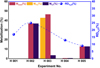 |
Fig. 10 Metallization degree vs reduction degree via HP during the HPSR process. |
3.3 Power input and reduction efficiency
As shown in Table 3, the average power supply during both pre-melting and the reduction stages is inversely correlated with feedstock composition and its smelting behavior. The highest average power draw was recorded for H 001, where the high melting point and low thermal conductivity of Cr2O3 necessitated more power and heat input (∼ 7 kW) to melt down the feedstock. Manual increase of the power supply via SCR controller setting in the transformer also helps stabilize plasma in the reduction step in which the gas composition and, therefore, the resistivity of the gas column undergoes a significant change. However, system modification with iron chips could not affect the required power input since similar slag forms over the molten metal in H 002. In contrast, there is a significant drop in this value in H 003–H 005 to less than 5 kW, highlighting the lower melting point and viscosity of slag and easier arc stabilization by the modifying slag composition. Moreover, fluctuation in the parameters relates to power input (I and V), leading to instability of the plasma arc considered with transition to the reduction stage. This phenomenon was controlled by lowering arc distance, increasing power supply, and modifying the slag composition.
Average power input during the HPSR process.
3.4 Slag-refractory interaction
The cross section of the produced slag in the synthetic mixture of the Cr2O3 was demonstrated in Figure 11. As shown, the slag consists of two areas with different chemical compositions. The chemical compositions of the matrix and highlighted precipitates were illustrated in Figures 12d–12f. Thermodynamic simulation of the interaction between slag with varying chemistries and magnesia-chromite refractory via FactSageTM was demonstrated in Figures 12a–12c. Evaluation of slag containing pure Cr2O3 (H 002) revealed minimal penetration of slag up to the melting point of Cr2O3. However, the abrupt rise of slag composition along the reaction interface discloses severe refractory corrosion in the extreme temperature. The possibility of achieving a low-temperature liquid phase by adding CaO to the slag composition (H 004) enables the onset of refractory corrosion from ∼2000 °C. In addition, a wide range of temperatures starting from 1800 °C could intensively start refractory invasion in the slag composition of H 005. Additionally, the influence of rising temperature on the instant drop of the MgO-rich phase (periclase) and spinels, indicated complete refractory dissolution and broke complex compounds of metal oxides in the slag-refractory interface.
The results of analyzing chemical composition by scanning electron microscopy (SEM), equipped with energy dispersive X-ray spectroscopy (EDS), were demonstrated in Figures 12d–12f. The results correspond to the average value of five different point scans from two dominant phases, identified as a matrix and precipitates evenly distributed within it. According to the results, the chemical composition of the matrix and precipitates is approximately similar for the single-component slag (H 002). However, slight dissolution of the molten Fe in the slag was led to the formation of the two low-meting point (matrix) and high melting point (precipitate) phases. On the other hand, higher operation temperature compared to conventional ferrochromium production process (SAF route)accelerated evaporation of the molten metallic bath and its subsequent trapping into the slag.
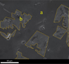 |
Fig. 11 SEM-SE image of H 005 slag cross section: (a) matrix, (b) precipitate. |
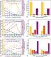 |
Fig. 12 Thermodynamic simulation of slag diffusion into the magnesia-chromite refractory for the slag sample composition of (a) H 002, (b) H 004, and (c) H 005 using FactSageTM 8.3, Database FactPS, FToxid, plus SEM-EDS analysis of the average concentration for different elements at (d) H 002, (e) H 004, and (f) H 005. |
4 Discussion
4.1 Reduction mechanism and feedstock chemistry
The recovery of chromium from metal oxide was described in equations (3) to (9). The reduction mechanism by HP and corresponding steps of metal recovery were demonstrated in Figure 2c, too. However, the electrical conductivity of the underlying melt and the chemical properties of different fluxes were disclosed as a significant influence on the reduction process. As shown in Figures 7 and 9b, although the presence of a molten metallic bath beneath the slag layer enhances thermal conductivity, a new challenge was introduced to the reduction mechanism. Several hypotheses based on the combination of the thermo-electromagnetic and interfacial phenomena could be considered for forming an arch-shaped metal and repelling slag to the walls of the crucible. Initially, electro vortex flow (EVF) that might be formed due to the electric current passing through the molten metal and its subsequent self-induced magnetic field, known as Lorenz force, leads to an arched profile. Secondly, thermal convection ensued from the temperature gradient between the high-temperature AAZ and the cooler crucible walls, which could cause asymmetric slag movement. In addition, the high melting point of the slag would lead to instant solidification on the crucible walls. Finally, the wetting angle of the molten metal with the refractory crucible is high, inhibiting uniform distribution of it along the crucible. Given the preference of plasma to remain stable at its initial ignition spot, where a thin layer of molten slag in the middle of arched slag enables better current flow between HGE and the underneath molten metal due to the closest arc distance to the conductive spot. This situation limited the kinetics of the reduction process since oxygen transport to the reaction interface and the interaction between reactants and reducing agents were challenging, as movement of the rest of the slag towards the AAZ was hampered. To address this issue, CaO was added into the feedstock in H 004 to form a low-temperature binary oxide mixture with Cr2O3, lowering the melting point and facilitating the formation of a homogeneous molten slag with less viscosity. In contrast, this modification decreased the hydrogen reduction degree to 13%, which is an even lower value compared to pure Cr2O3. The addition of CaO solely can lead to the formation of a refractory spinel phase with Cr2O3 and prevent further reduction progress, especially at lower Cr2O3 concentration. On the other hand, considering the high melting point of both CaO (2613 °C) and Cr2O3, homogenous melting of this system is impossible, and the final reduction degree was negatively impacted by this issue. Further optimization by adjusting basicity was attempted in H 005. The incorporated flux content at the beginning of the trial was set to 40% with an initial basicity ratio of B2 = 1.67. This basic mixture was aimed to employ SiO2 as a network former and CaO as a network modifier, intending to lower the viscosity and melting temperature. However, the arching phenomenon recurred, and much of the generated slag was repelled from the AAZ to the side wall of the crucible, rapidly sintered, and solidified regarding the moderate radiative heat loss. Consequently, the  dropped to 9%, highlighting the restrictions of excess iron chips and flux addition on the slag stabilization in the molten state. While iron chips form a molten bath underneath the slag due to the higher density, they do not help dissolve the feedstock and lower their melting point in the first smelting stage. Hence, the produced inhomogeneous, refractory slag lacks sufficient contact with the reducing agents in AAZ to support efficient reduction. In contrast, mixing iron oxide (of the iron ore) with Cr2O3, as conducted in H 003, facilitates the initial dissolution of Cr2O3 and later contribution of it in forming homogenous slag. This condition is favorable due to the direct exposure of the molten slag to the AAZ and the opportunity to dissolve the other synthetic additives (oxides and fluorides) and to maintain melting point in the system low even after the primary reduction of the iron oxide from the slag. As shown in Figure 8c, the mixture of pure Cr2O3 with iron ore enhances hydrogen utilization, leading to significant metallization. While iron oxide assists in improving plasma arc stability and rapid melting, the primary reduction of it makes it difficult to determine the exact reduction degree via MS data only. Therefore, the calculation of the total
  is only possible through the analysis and separation of this number for each of the recovered metal oxide required further characterization.
4.2 Slag analysis and refractory corrosion
Thermodynamic assessment of the slag-refractory interdiffusion is a prerequisite for understanding the effect of the subsequent chemical reactions on the refractory corrosion. In addition to the phase diagrams, which are sometimes unavailable for the complex systems, the thermodynamic database of FactSageTM could help predict the stability of the chosen refractory against different slag compositions. Jung et al. [21] have simulated the penetration of the VOD slag (CaO-SiO2-Al2O3) into the magnesia-chromite refractory. Severe corrosion by the slag and formation of complex calcium silicate spinels were reported. The direct influence of the slag basicity on the refractory degradation was confirmed through the different studies [21, 22]. As previously discussed, magnesia-chromite refractory was employed to hold the molten iron for the slag samples at H 002, H 004, and H 005. Therefore, the thermodynamic simulation of the slag-refractory for various slag compositions at different operation temperatures is demonstrated in Figures 11a–11c. Moreover, the slag composition for each of the mentioned experiments has been analyzed using SEM-EDS to evaluate probable impurities resulting from refractory dissolution into the slag composition. The results were demonstrated in Figures 11d–11f. As shown in Figure 11a, periclase (MgO-rich phase) and spinel do not change considerably before the melting point of the pure Cr2O3, and, subsequently, the slag penetration in the slag-refractory interface is very low. However, the instant drop in the refractory phase beside the completely dominant slag phase at 2500 °C predicts intensive corrosion of the refractory. By addition of CaO to pure Cr2O3 (Fig. 11b), slag diffusion into the refractory would be accelerated due to the presence of the liquid slag at a lower temperature. Hence, 2000 °C can be considered as the upper limit for the intensive corrosion of the refractory. The refractory dissolution into the slag would get much more intensive by adjusting the basicity of the system to B2=1.67 (Fig. 11c). Different levels of refractory corrosion were predicted to take place in various ranges of the temperature for smelting operations. However, the average results of point scans in the SEM-EDS analysis (Figs. 11d–11f) disclose that nearly no refractory elements were dissolved into the slag. Such a desired situation can only be explained by two reasons. First, the contact area in the slag-refractory interface was negligible since a high portion of the refractory crucible was filled with molten iron with a low melting point. Second, due to the concentration of very high operation temperature only in the AAZ and inhomogeneous slag temperature, it did not exceed the mentioned temperature limit for intensive corrosion of the refractory in the crucible walls. However, further investigations are required to evaluate the stability of the magnesia-chromite refractory crucible against more complex slag mixtures without interference from the iron chips. Moreover, the results of SEM-EDS analysis reveal the presence of two major phases in the produced slag. While these phases are not chemically separable for H 002, the presence of iron oxide and CaO indicated the formation of complex spinels in the system (H 004 and H 005). The elemental characterization reveals FeCr2O4 and CaCr2O4 as dominant spinels in the matrix and precipitates, respectively. It can be interpreted that iron oxide sacrifices itself due to its higher tendency for spinel formation with present CaO in the pre-melting stage. However, as iron oxide concentration decreases in the reduction stage, CaO starts to produce stable spinel of CaCr2O4 with available Cr2O3, hindering further reduction. In addition, the generation of precipitates limits the contact area between the reducing agent and the slag matrix. Such a claim was asserted based on the existence of iron oxide in the system, despite the molten slag has been exposed to plasma species for approximately one hour.
5 Conclusion
This investigation studied the reduction of Cr2O3 in various configurations, such as pure, synthetic (with fluxes and iron oxide), and in the presence of iron chips. The aim of such modification was to optimize the reduction efficiency, slag fluidity, and energy consumption. Thermodynamic calculations revealed that despite the favorable decomposition potential of the many fluxes at the plasma operating temperature (∼ 2500 °C), the formation of the stable spinels is the main challenge hindering the further reduction. Among all candidate fluxes, wüstite showed promising properties due to providing relatively low melting points, high electrical conductivity, and limited affinity for spinel formation (not negatively influence on the activity of Cr2O3).
The results of the conducted tests disclosed the dependence of the reduction efficiency on the presence of the metallic additive, slag composition, pre-melting condition, and the reactor design. Efforts to improve such factors by various additives were partially successful. Formation of the binary and ternary systems with lime and silica lowered the reduction efficiency to 13% and 9% because of the challenges caused by the stable spinels and arched slag, which hindered further reduction. The major issues were due to the Lorenz force ensued from EVF, thermal convection between AAZ and crucible walls, slag with a high melting point, and a lower wetting angle in the metal-refractory crucible interface. On the other hand, the obtained results from metallization degree revealed the negative impact of fluxes on the reduction efficiency. Such an effect was intensified by the presence of iron oxide in the system due to the thermodynamic preference for reduction of iron oxide prior to Cr2O3. In addition, the energy consumption analysis revealed the direct relation between the formation of fully molten and homogenous slag and lowering the required power input. This relation disclosed the importance of the thermal conductivity and melting point of the slag with arc stability and the efficiency of the smelting process.
The future investigations should focus on increasing the efficiency of the reduction process by thermodynamic study of the activity and melting point in alkaline and acidic systems to lower the viscosity of the slag while hindering stable spinel formation, which limits the activity of Cr2O3 in the slag and drops reduction efficiency. On the other hand, while iron oxide was proven to assist in the pre-melting step, the consistency of the melt should be ensured via controlling other fluxes for the next studies.
Acknowledgments
The author also thanks the HELIOS—HORIZON-MSCA DN consortium for financial support and collaborative exchanges.
Funding
This project has received funding from the European Union’s Horizon Europe research and innovation program under the Marie Skłodowska-Curie Grant Agreement No. 101120068.
Conflicts of interest
The authors have nothing to disclose.
Data availability statement
This article has no associated data generated and/or analyzed / Data associated with this article cannot be disclosed due to legal/ethical/other reason.
Author contribution statement
Conceptualization, M. Jafarzadeh and M. A. Zarl; Methodology, M. Jafarzadeh, M. Saraçoğlu, M. A. Zarl, and D. Ernst; Software, M. Jafarzadeh; Validation, M. Jafarzadeh, M. Saraçoğlu, M. A. Zarl, D. Ernst, and S. K. Michelic; Formal Analysis, M. Jafarzadeh and M. A. Zarl; Investigation, M. Jafarzadeh, M. Saraçoğlu; Resources, M. Jafarzadeh; Data Curation, M. Jafarzadeh; Writing—Original Draft Preparation, M. Jafarzadeh; Writing—Review & Editing, M. Jafarzadeh, M. A. Zarl, D. Ernst, and S. K. Michelic; Visualization, M. Jafarzadeh; Supervision, M. A. Zarl, D. Ernst, and S. K. Michelic; Project Administration, M. A. Zarl; Funding Acquisition, M. A. Zarl.
References
- C.A. Pickles, S.S. Wang, A. McLean et al., A new route to stainless steel by the reduction of chromite ore fines in an extended arc flash reactor, ISIJ Int. 18, 369–378 (1978) [Google Scholar]
- I.J. Geldenhuys, Aspects of DC chromite smelting at MINTEK—an overview: 13th International Ferroalloys Congress, INFACON XIII (2013) [Google Scholar]
- D. Tandersen, A. Taimullah, I. Islam et al., Rapid and sustainable ferrochrome production from chromite ore by hydrogen plasma smelting reduction, Plasma Chem. Plasma Process. 45, 1045–1062 (2025) [Google Scholar]
- P.R. Taylor, W. Wang, A laboratory investigation of the reduction of a laboratory investigation of the reduction of chromium oxide by a reverse-polarity DC plasma-driven molten oxide electrolysis process plasma-driven molten oxide electrolysis process, Plasma Chem. Plasma Process. 22, 387–400 (2002) [Google Scholar]
- P.R. Taylor, W. Wang, Producing carbon-free Cr/Cr alloys using a reverse-polarity transferred-arc plasma, JOM 53, 25–26 (2001) [Google Scholar]
- H. Dalaker, E.W. Hovig, Hydrogen plasma-based reduction of metal oxides, in: C. Fleuriault, J.D. Steenkamp, D. Gregurek, J.F. White, Q.G. Reynolds, P.J. Mackey, S.A.C. Hockaday (Eds.), TMS Annual Meeting & Exhibition, Springer, Cham, pp. 85–94 (2023) [Google Scholar]
- K.C. Sabat, A.B. Murphy, Hydrogen plasma processing of iron ore, Metall. Mater. Trans. B 48, 1561–1594 (2017) [Google Scholar]
- Y. Zhang, W.Z. Ding, S. Guo et al., Reduction of metal oxide in nonequilibrium hydrogen plasma, Chin. J. Nonferrous Met. 14, 317–321 (2004) [Google Scholar]
- K.C. Sabat, P. Rajput, R.K. Paramguru et al., Reduction of oxide minerals by hydrogen plasma: an overview, Plasma Chem. Plasma Process. 34, 1–23 (2014) [Google Scholar]
- D. Ernst, M.A. Zarl, J. Cejka et al., A new methodological approach on the characterization of optimal charging rates at the hydrogen plasma smelting reduction process part 2: results, Materials (Basel) 15, 4065 (2022) [Google Scholar]
- M.J. Gallagher, A. Fridman, Chapter 8 - plasma reforming for H2-rich synthesis gas, in: D. Shekhawat, J.J. Spivey, D.A. Berry (Eds.), Technologies for Fuel Processing, Elsevier, 2011, pp. 223–259 [Google Scholar]
- D.R. Mac Rae (Eds.), Plasma-arc technology for ferroalloys, Part II: 6th international ferroalloys congress, SAIMM, 1992, pp. 21–35 [Google Scholar]
- K. Kamiya, N. Kitahara, I. Morinaka et al., Reduction of molten iron oxide and FeO bearing slags by H2-Ar plasma, ISIJ Int. 24, 7–16 (1984) [Google Scholar]
- H. Oterdoom, M. Reuter, J. Zietsman, DC ferrochrome smelting: the arcing zone and its influence on energy transport and exergy dissipation, Metall. Mater. Trans. B 56, 890–912 (2025) [Google Scholar]
- P.R. Taylor, W. Wang, Reverse-polarity direct current plasma-driven electro-reduction of refractory metals in molten oxide melts, Min. Metall. Explor. 21, 103–109 (2004) [Google Scholar]
- M.A. Zarl, M.A. Farkas, J. Schenk, A study on the stability fields of arc plasma in the HPSR process, Metals 10, 1394 (2020) [Google Scholar]
- A. Barnes, C. Finn, S. Algie, The prereduction and smelting of chromite concentrate of low chromium-to-iron ratio, 49–54 (1983) [Google Scholar]
- J. Davies, D. Paktunc, JJ. Ramos-Hernandez et al., The use of hydrogen as a potential reductant in the chromite smelting industry, Minerals, 12, 534 (2022) [Google Scholar]
- Z. Zulhan, B. Hakim, Y. Hendrawan, W.D. Sulakso, D. Tandersen, A. Taimullah, M.I. Islam, Y. Makhambetov, T. Hidayat, (Eds.), Reconsidering Hydrogen Plasma Reactor as a Sustainable Solution for Green Metals Production, ISHM, 2024 [Google Scholar]
- A. Taimullah, I. Islam, D. Tandersen et al., Direct and sustainable stainless steelmaking from nickel and chromite ores by hydrogen plasma smelting reduction, Int. J. Miner. Metall. Mater. 32, 1881–1892 (2025) [Google Scholar]
- I-H. Jung, S. Decterov, A. Pelton, Computer application of thermodynamic database to corrosion of refractories, UNITECR, Ecole25825, 2003, pp. 252–255 [Google Scholar]
- I-H. Jung, Overview of the applications of thermodynamic databases to steelmaking processes, Calphad. 34, 332–362 (2010) [Google Scholar]
Cite this article as: Mohammad Jafarzadeh, Mert Saraçoğlu, Michael Andreas Zarl, Daniel Ernst, Susanne Katharina Michelic, Hydrogen Plasma Smelting Reduction of Cr2O3/Chromite: The First Step to Direct and Sustainable Production of Stainless Steel, Matériaux & Techniques 114, 306 (2026), https://doi.org/10.1051/mattech/2026003
All Tables
All Figures
|
Fig. 1 Dissociation and ionization of plasma-forming gases over the temperature at 100 kPa (FactSageTM 8.3, Database FactPS). |
| In the text | |
|
Fig. 2 The reduction process of metal oxides via the HPSR process, including (a) reactor showcase, (b) first ignition of thermal plasma arc, and (c) reduction process [13]. |
| In the text | |
|
Fig. 3 Decomposition potential (volts) of the metal oxides in a pure state close to the melting point [15]. |
| In the text | |
|
Fig. 4 Viscosity of molten slag (single mineral oxides and complex systems) vs. temperature (FactSageTM 8.3, Database FactPS & FToxid). |
| In the text | |
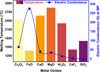 |
Fig. 5 Melting temperature and specific conductance of metal oxides at melting point [15]. |
| In the text | |
|
Fig. 6 Gibbs free energy of the formation for the spinels in the binary systems (FactSageTM 8.3, Database FToxid). |
| In the text | |
|
Fig. 7 Schematic reduction procedure with the HPSR process in (a) presence (refractory crucible) and (b) lack (steel crucible) of iron chips in the feedstock. |
| In the text | |
|
Fig. 8 H2 content in exhaust gas recorded by MS. |
| In the text | |
|
Fig. 9 The cross-section of products after the smelting process for the samples containing (a) pure Cr2O3, (b) iron chips and feedstocks, and (c) feedstock with iron ore as an additive. |
| In the text | |
|
Fig. 10 Metallization degree vs reduction degree via HP during the HPSR process. |
| In the text | |
|
Fig. 11 SEM-SE image of H 005 slag cross section: (a) matrix, (b) precipitate. |
| In the text | |
|
Fig. 12 Thermodynamic simulation of slag diffusion into the magnesia-chromite refractory for the slag sample composition of (a) H 002, (b) H 004, and (c) H 005 using FactSageTM 8.3, Database FactPS, FToxid, plus SEM-EDS analysis of the average concentration for different elements at (d) H 002, (e) H 004, and (f) H 005. |
| In the text | |
Current usage metrics show cumulative count of Article Views (full-text article views including HTML views, PDF and ePub downloads, according to the available data) and Abstracts Views on Vision4Press platform.
Data correspond to usage on the plateform after 2015. The current usage metrics is available 48-96 hours after online publication and is updated daily on week days.
Initial download of the metrics may take a while.