")
")
| Issue |
Matériaux & Techniques
Volume 114, Number 1, 2026
Special Issue on ‘Advances in Steel Technologies’, edited by Carlo Mapelli, Silvia Barella and Riccardo Carli
|
|
|---|---|---|
| Article Number | 105 | |
| Number of page(s) | 13 | |
| DOI | https://doi.org/10.1051/mattech/2025029 | |
| Published online | 11 March 2026 | |
Original Article
Advancing hydrogen plasma smelting reduction: Experimental insights from a pilot plant
1
K1-MET GmbH, Stahlstraße 14, 4020 Linz, Austria
2
Technical University of Leoben, Franz Josef-Straße 18, 8700 Leoben, Austria
* email: This email address is being protected from spambots. You need JavaScript enabled to view it.
Received:
25
August
2025
Accepted:
12
December
2025
Abstract
The hydrogen plasma smelting reduction process is a promising technology for sustainable steel production from iron ores, utilizing molecular, atomic and ionized hydrogen as reducing agents. It is operated in a gas-tight direct-current electric arc furnace with a hollow graphite cathode for material and gas feeding. To investigate scale-up parameters, a pilot plant with a capacity of 100 kg of iron ore per trial has been built at the site of voestalpine Stahl Donawitz GmbH in Leoben, Austria, and is operated by K1-MET GmbH, Linz, Austria. This study describes the pilot setup in detail and examines the impact of selected parameters on the reduction process. Therefore, thermal insulation is applied to the vessel to mitigate heat losses and enable higher bath temperatures. Furthermore, different crucible refractory materials are evaluated for their wear characteristics. Additionally, varying input materials, including pre-reduced ore, are processed and their influence on the reduction kinetics is discussed. It is observed, that the gangue content significantly affects the reduction process. Thermally insulating the vessel leads to better separation of the slag and metal phases as well as lower energy consumption. The refractory wear is reduced by using phosphate-bonded magnesia lining. These combined results provide insights into the optimization of process conditions for hydrogen plasma smelting reduction at pilot scale.
Key words: hydrogen plasma smelting reduction (HPSR) / pilot plant / alternative ironmaking / sustainable steelmaking / reduction kinetics / refractory lining
© B. Adami et al., 2026
 This is an Open Access article distributed under the terms of the Creative Commons Attribution License (https://creativecommons.org/licenses/by/4.0), which permits unrestricted use, distribution, and reproduction in any medium, provided the original work is properly cited.
1 Introduction
The steel industry is one of the largest industrial sources of greenhouse gas emissions, responsible for around 7 % of global emissions. The traditional blast furnace–basic oxygen furnace route heavily relies on coke as both an energy source and a reducing agent. To meet climate targets and move towards climate-neutral steel production, many new technologies that minimize the utilization of fossil carbon are under development [1].
One such promising approach is hydrogen plasma smelting reduction (HPSR). It is a high-temperature process that uses hydrogen and plasma energy to melt and reduce iron ores. The HPSR concept has been under development at the Technical University of Leoben, Leoben, Austria, since the early 1990s. Initial laboratory experiments showed that hydrogen plasmas can reduce iron oxides efficiently, thanks to the high reactivity of excited, atomic and ionized hydrogen as well as the intense heat of the plasma. These early results demonstrated the potential for a one-step, carbon-lean reduction process, where only minimal carbon is introduced into the process by the wear of the graphite cathode [2].
A detailed description of the HPSR process and the basic laboratory setup are omitted at this point since they have been published already multiple times previously [3–5]. Besides the research conducted in Leoben, Austria, works using different laboratory-scale installations worldwide were also covering this process [6–9].
A pilot plant has been built at the site of voestalpine Stahl Donawitz GmbH, Leoben, Austria, and is operated since its commissioning in 2021 by K1-MET GmbH, Linz, Austria. The aim is to bring the technology closer to industrial application. It currently has a technology readiness level (TRL) of 5 [10], with a roadmap to TRL 6–7 at the end of 2026. Therefore, many aspects of the process are under investigation, a few of which are presented in this work. After a description of the pilot reactor and the conducted trials, the results of visual investigations and the general reduction behavior are summarized. This is followed by studying the modification of the crucible’s refractory material as well as changes to the thermal characteristics of the reactor. Finally, the introduction of pre-reduced iron ores into the process is examined. This is important, because in the future upscaling the hot, hydrogen-containing exhaust gas of the HPSR reactor should be used to pre-heat and pre-reduce the ore feed for enhanced thermal and hydrogen efficiency [11].
2 Description of the HPSR pilot reactor
The design of the HPSR pilot reactor is based on the existing laboratory setup, scaled-up roughly 1000-fold. The schematic of the reactor as well as a photograph of the pilot plant are shown in Figure 1. The roofed main steel structure is 8.6 m long, 6.4 m wide and 11.9 m high, consisting of two floors as well as the ground level.
Amongst other components it houses the main reactor, which basically consists of a lower vessel (A), an upper vessel (B) and a central plasma torch (C). The latter is movable vertically by a spindle drive, which is connected to the lift arms (D) and uses a hollow graphite tip (E) as the cathode for the transferred arc. The hollow design of the plasma torch allows for the charging of the iron ore fines together with the process gases through the cathode directly in the vicinity of the plasma. The iron ore fines and additives like burnt lime or silica are stored in two separate bunkers located above the reactor. Those bunkers are equipped with screw conveyors at their bottoms and feed into the central gas supply line, which is directly connected to the cathode.
The lower vessel acts as the crucible, houses the anode (F) and is removable for maintenance as well as trial preparation. In the lid (G) of the stationary upper vessel, the plasma torch, a viewport (H) and three auxiliary blind flanges (I) are installed. On the viewport, a camera (J) is positioned so that the visual behavior of the arc can be recorded. A slight nitrogen purge flow (K) is introduced at the viewport to prevent dust deposition on the glass. A similar system is applied to the interface between the cathode holder (L) and its feedthrough (M) at the lid, which also minimizes dust deposition on the moving parts. A nitrogen flow rate of around 150 Nl/min is constantly introduced throughout the process for the different nitrogen purges. Additionally, an ethanol spraying nozzle is installed to wash deposited material off the viewport glass if necessary.
The off-gas port (N) is located in the side wall of the upper vessel near the top of the reactor. In the off-gas duct near the reactor outlet is a sampling port for a mass spectrometer installed, which, in principle, allows continuous measurement of the exhaust gas composition. Unfortunately, the spectrometer was not working properly when the presented trials were conducted. Therefore, no results regarding the off-gas analysis can be given. After the sampling position, the exhaust gas enters a water spray tower for cooling and dedusting before it is released 2 m above the highest point of the steel structure.
For safety reasons, the reactor is always operated at a slight overpressure of 150 mbar. Therefore, a flange for redundant pressure measurements is installed in its sidewall slightly above the top of the crucible. The pressure is controlled by a valve in the off-gas duct just before the stack. Using this system, in case of a slight leakage, hydrogen will leave the reactor, but oxygen ingress is prevented. If the escaping hydrogen is cold, it is immediately diluted by the surrounding air. Otherwise, it ignites and burns off. In any case, the formation of an explosive atmosphere inside the confined space of the reactor is not possible with this operation concept.
Contrary to the lower vessel, the upper vessel, the off-gas port, the cathode feed through and the plasma torch are not insulated with refractory material. To withstand the high temperatures, they are water-cooled (O) in parallel loops to maximize the cooling power from a closed main supply. This also applies to the anode. To investigate the effect of a different thermal insulation concept, the upper vessel was lined with 275 mm of insulating fibrous mats (P) on all inner surfaces for some trials. The lower vessel is lined with a work layer (Q) of magnesia-alumina spinel (MA spinel) pre-fabricated shapes and an outer insulating lining of mullite castable (R). Outside the steel shell, fibrous mats (S) are mounted to increase the insulation of the crucible. During the campaign, the wear lining of the crucible was changed to a phosphate-bonded magnesia (MgO-P) castable to study the influence of the refractory material. The firing of the refractory is done in a standard ladle heater fed with natural gas, positioned around 5 m away from the reactor. A track and lifting system exists to move the lower vessel between the two devices easily. The ladle heater is not only used for initially firing the lining, but also pre-heating the crucible before each trial to minimize thermal shocks. To prevent damage to the refractory because of water vapor condensation at possible cold-spots at the shell of the lower vessel, its cooling-water (T) temperature is carefully controlled. Therefore, it has a separate pressurized cooling-water loop with a tempering unit to allow for temperatures slightly above 100 °C. Four thermocouples (U) are attached to the lower vessel to monitor the refractory temperature. The pin-type anode at the bottom of the vessel can optionally be equipped with a purging plug, which was not in operation during the trials presented in this work. The electric circuit is closed via the whole reactor shell, which has ground potential.
The whole process is controlled and monitored electronically with tailor-made software. Besides many functions, such as automatically controlling the reactor pressure for safety reasons, as mentioned above, it also features a voltage-control mode. When active, the cathode is automatically moved vertically according to the set target voltage of the arc. A maximum direct current of 2200 A at a maximum voltage of 360 V can be supplied by the transformer. However, an active electric filter to minimize grid disturbance and the plasma torch limit the operation to a maximum power of 350 kW. The possible gases to operate with are hydrogen as the reducing agent, argon for the stabilization of the plasma and nitrogen for increased melting rates during the pre-melting stage. The flows of those gases can be controlled individually by thermal mass flow controllers in the range of 0–4000 Nl/min each. The iron ore fines and additives can be charged at a rate of 0–2.5 kg/min and 0–0.15 kg/min, respectively. The operable grain size range for both charging systems is 0.1–0.5 mm. It is also possible to run the process batch-wise, which allows the processing of larger grain sizes. This was the case for the trials presented below. The entire setup has a processing capacity of around 100 kg of iron ore per trial. As it is not possible to tap the melt, the reactor must be dismantled to obtain the produced slag and metal phases. Those can then be broken out mechanically with pneumatic hammers.
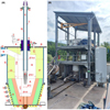 |
Fig. 1 (A) Schematic cross section (all dimensions in mm) and (B) photograph of the HPSR pilot plant. |
3 Materials and methods
In total, five trials were conducted. It must be noted that the trials were not optimized in their parameters since they are mostly aimed towards introducing the HPSR process at the scale of a pilot plant and providing first results thereof. The main variations were in the composition of the input material, the crucible refractory material and the insulation of the upper vessel. The iron-bearing materials (IBMs) were two different sinters, one grade of pellets and self-produced pre-reduced slag, because high-quality pre-reduced ores were unavailable at the quantity required. Due to its production method by previous trials, the pre-reduced material contains increased amounts of gangue components, since they were concentrated from their initial levels because of the reduction of iron oxides from the slag. Regarding the grain sizes, 85 % of the sinter material was in the range of 5–50 mm, 90 % of the pellets were between 8 mm and 18 mm. The pre-reduced crushed slag consisted of pieces up to 70 mm. Burnt lime, which is assumed to consist only of CaO, was added in some trials to vary the basicity of the charged material. The wear lining of the crucible consisted either of MA spinel or MgO-P. The upper vessel was insulated on the inner side with fibrous mats for some trials. While hydrogen and argon flow rates vary, the ratio between the two plasma gases is kept constant at 3:1, equivalent to a hydrogen content of 75 vol. %. This value was chosen based on operational experience with the pilot plant as a balance between a high argon content for plasma stability [12] and a high hydrogen content for faster reduction [13]. All experiments were operated at the maximum electrical power input, which was achievable without overheating some components, especially the plasma torch. Table 1 summarizes the different experimental setups. The average power input P is defined as
 (1)
(1)
where u (t) indicates the voltage and i (t) the current varying over the experiment time t [14]. Therein, the start and end of the reduction step are denoted by tstart and tfinish, respectively.
The composition of the IBMs is given in Table 2, together with their basicity [5]
 (2)
(2)
Therein, wi is denoting the mass fraction of compound i. Furthermore, the initial reduction degrees
 (3)
(3)
of the feeds are stated, whose calculation is derived from [15]. Therein,  denotes the mass of oxygen bound to the iron contained in the input material and
  the maximum value of this quantity, i.e. the mass of oxygen bound to iron if all Fe would be present as Fe2O3.
The overall procedure for all trials was roughly the same and can be split into six steps: preparation, crucible pre-heating, pre-melting under inert plasma, reduction of the melt with hydrogen plasma, controlled process shut-down and post-processing. Even though experiments with continuous charging of the iron ores are possible at the plant, the raw materials for all trials presented in this work were pre-charged as a single batch into the crucible. If desired, burnt lime was homogeneously mixed with the bulk during charging. It has to be noted that the bottom of the crucible was covered with steel to protect the refractory material. This is achieved by charging around 60 kg of steel scrap before the main charge if no metal from previous trials remained in the crucible. To prevent reoxidation of the FeO contained in the pre-reduced material, the IBM of trial no. 5 was not charged into the crucible before vessel pre-heating, but afterwards. However, to ensure ignition of the plasma, a steel pin with a mass of 6 kg was welded centrally into the crucible in this case.
The next step is to pre-heat the whole lower vessel for around 20–24 h according to a certain temperature profile to prevent thermal shocks to the refractory. After pre-heating, the lower vessel is combined with the upper vessel. For trial no. 5, the pre-reduced material was charged into the crucible during this time of vessel manipulation.
Following the checks for gas-tightness, the whole reactor is purged with nitrogen to remove any remaining air and produce an inert atmosphere. It was tried to accomplish this step as fast as possible in the case of trial no. 5 to minimize reoxidation of the charge. Then, the ignition step follows. A slight argon flow rate of usually around 200–400 Nl/min is set and a target current of approximately 1000–1200 A is applied. This means that the cathode is now at its maximum negative potential. While lowering the cathode slowly, the arc ignites spontaneously if the potential difference is large enough to bridge the gap between the cathode and the charged material. Because the raw material is electrically conductive at the prevailing temperatures, the arc ignites directly at contact. In contrast to the laboratory facility [4, 5], no ignition aids are necessary for standard trials. When a slight melt pool has formed and the target current is reached, the cathode is raised and nitrogen is mixed to the plasma gas for increased heating rates. The voltage needs to be carefully monitored so that it does not exceed the maximum voltage the transformer can supply. Otherwise, the arc will extinguish. This is done mainly by controlling the distance between the cathode and the melt so that the arc voltage is around 150 V on average.
When no more solid phases are observed in the melt via the viewport camera, the reduction process is started by switching the plasma gas to the desired hydrogen-argon mixture. The voltage during the reduction process is controlled to be around 120 V on average. All experiments were deliberately aborted in a semi-reduced state after 90 min of reduction time to identify differences in the reduction kinetics between the setups more easily. Accidentally, trial no. 5 was aborted after a reduction time of 95 min, which is only a time difference of 6 % and should therefore not significantly affect the results.
The process of controlled shut-down of an experiment begins with the change of the plasma composition to pure argon. Then, the current is gradually reduced over several minutes and simultaneously the cathode is raised slowly until the arc disconnects and therefore the plasma extinguishes. This should allow dispersed metal droplets to coagulate and the slag and metal phases to separate. After the end of the process, the reactor is flushed with nitrogen to obtain an inert atmosphere, thereby preventing reoxidation of the reduction products. It is left in this stage with the cooling water flows active for around 18–30 h.
Finally, the lower vessel is removed from the reactor and the slag and metal phases are broken out mechanically with a pneumatic hammer. Due to the fusion of the metal phase called regulus with the pins of the bottom anode, it is not always possible to extract the contents of the crucible in their entirety. The metal then remains in the crucible and acts as the protection layer for the bottom refractory, as mentioned above. The masses of the broken-out phases are recorded. Some chunks of the slag are mixed, ground and analyzed chemically. The overall elemental composition is determined via X-ray spectroscopy with the results converted to the corresponding oxides. LECO analysis is used for measuring sulfur. The distribution of the oxidation states of the iron species is obtained wet-chemically by titration. Since the silica content of the slag influences this method, the amount of each iron species is then calculated based on this distribution relative to the total iron content obtained with X-ray spectroscopy. The regulus was cut and machined at a relatively flat location and analyzed by spark optical emission spectroscopy.
Overview of the parameters of the conducted trials.
Composition of the IBMs.
4 Results and discussion
This section is split into six parts. The first one is about the observations made visually during the trials and while breaking out the crucible contents. In the second part, the mass balance is presented, followed by the determination of the reduction kinetics and the comparison thereof to a laboratory scale HPSR reactor. The fifth and sixth sections contain the results obtained by comparing the different upper vessel insulation concepts and refractory materials, respectively.
4.1 Visual investigation
To provide visual insights into the process, Figure 2 shows exemplary snapshots of the video recorded by the camera positioned at the viewport during trial no. 4. Due to the upper vessel insulation, the entire surface of the crucible is not visible. In the center, the graphite cathode can be seen, just below its water-cooled steel holder. The whole cathode system can be moved vertically during the process.
Before ignition (A), the externally pre-heated sinter chunks are well observable. The darker, cooler spot in the center below the cathode originates from the nitrogen flow necessary to inertize the reactor.
During pre-melting (B), with an argon-nitrogen plasma, a melt pool forms in the center below the cathode. The melt surface is lower than that for the solid bed due to its higher density than the loosely packed material. For this reason, the cathode is moved downwards to keep the voltage in a stable region. Measuring the distance between the cathode and the bath is challenging due to the varying bath height and cathode wear. During pre-melting, a cathode-bath distance of around 5–15 cm can be estimated, depending on the gas composition and the power input. Since the camera automatically controls the brightness level of the recorded video, the previously glowing bed is now dark due to the relatively strong light emission of the plasma. Over time, the melt pool expands either by directly melting the solids or via avalanches of bulk material sliding into the bath. Chunks of unmolten sinter are observable below and to the right of the cathode.
Once a fully molten slag bath is obtained (C) the plasma burns very stably. The arc moves slowly around the bath and its column is rather straight.
When switching to the reduction step (D), the plasma gas composition is changed to an argon-hydrogen mixture and the arc becomes more unstable. Additionally, the cathode needs to be lowered further to account for the increased voltage drop. It results from the higher resistivity of the plasma column due to the energy needed for the dissociation of hydrogen molecules [16]. The estimated distance between the cathode and the bath is less than 5 cm for the reduction step. A change in the color of the bath is observable, which originates in the camera automatically adjusting the video brightness to the changing light emission behavior of the different plasmas [5].
Sometimes, a formation of solid layers on the melt surface is noticeable during reduction (E). The reason for this can either be the operational requirement to reduce the power to prevent overheating of the cathode holder, thereby lowering the melt temperature, or the formation and precipitation of high-melting compounds. Usually, those solid phases melt again when the plasma moves and burns directly on or near them. The extent of the formation of such solid phases varies between the trials. It was stronger in trials no. 1 and 2, indicating that insulating the upper vessel aids in obtaining higher surface temperatures, which is as expected.
When ending the reduction step (F) a color change in the bath is observed again due to the automatic brightness control of the camera and the different emission behavior of the elements, since the plasma is now pure argon. The reduction in power allows for the melt to solidify, which can be seen to the left of the cathode. Some bubble formation due to the decrease in the melt’s solubility for gases during cooling [17] is observable to the right of the cathode.
Figure 3 shows photographs of the crucible after trial no. 4 and before breaking out its contents as an example for all conducted trials. It can be observed that the slag surface is not even (A). This is because during solidification, material from underneath the already partially solid surface rises to the top. The reason for this might be temperature gradients in the melt, which influence their density. Furthermore, the decline in the solubility of gases during cooling [17] also facilitates bath movement by bubble formation.
An indication that this mechanism is relevant is visible in subfigure (B). It shows the cross-section of a slag lump directly below the surface. The left side is oriented to the crucible wall and the right side to its center. A large, entrapped gas pore can be seen directly below the surface and the bulk of the sample is also very porous. It was easy to break out this upper portion of the slag due to its brittleness.
The shape of the regulus (C) is not a compact nugget but more like a relatively flat disk with holes.
Particularly interesting is that a layer of slag (D) was also below the metal. At the bottom of this layer, unmolten sinter is observable directly above the protective steel disk, which indicates that a full melt pool could not be established. This layer was very hard and difficult to break out. It also contained some dispersed metallic droplets.
The other experiments basically resulted in the same layered structure of the crucible contents. However, the obtained reguli of the trials no. 1 and 2 were more irregularly shaped. Moreover, the slag contained many more and larger metallic droplets, some of which were found below and above the produced metal.
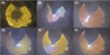 |
Fig. 2 Visual insights into trial no. 4: (A) before ignition, (B) and (C) during pre-melting, (D) and (E) during reduction, (F) during controlled process ending. |
 |
Fig. 3 Photographs of (A) the crucible contents before breaking out, (B) a sample of the slag above the regulus, (C) the metallic regulus and (D) a sample of the slag below the regulus for trial no. 4. |
4.2 Mass balances
The compositions of the obtained slags as well as the produced metals for the different trials are shown in Table 3. Due to the irregular shape and porosity of the metal pieces produced in trials no. 1 and 2, their chemical composition could not be measured with the optical emission spectrometer without extensive sample preparation. This was omitted since the reguli for the other trials consisted of nearly pure iron. In the further evaluation of all trials, the obtained metal is treated as if it was exactly 100 wt. % Fe for simplicity. The traces of carbon that were detected are most likely originating from measurement errors, since accurately measuring the carbon content at such low levels near the detection limit of the spectrometer is difficult. Notably, impurities like sulfur and phosphorus are also only present in very low quantities, even though their initial concentrations were high in some of the input materials. This is as expected, because laboratory-scale experiments show that low trace element contents in the produced metal are achievable with certain process conditions [5, 8].
To check the obtained quantities of the phases, a mass balance for each trial is necessary. For simplicity, it is assumed that only iron oxides are reduced in the HPSR process. This allows the calculation of the removed oxygen mass
 (4)
(4)
with  denoting the mass of i in the phase j. Now, the mass of the theoretically formed regulus can be estimated via the oxygen balance:
See equation (5) below.
 (5)
(5)
Therein, the molar masses Mi of iron and oxygen are 55.845 g/mol and 15.9994 g/mol, respectively [18]. It is assumed that the oxygen is reduced first from Fe2O3 until no more is present and then from FeO as described by the following two equations [19]:
 (6)
(6)
 (7)
(7)
This is important in trial no. 5, since there is more oxygen removed than originally bound to the contained three-valent iron. The protective steel for the refractory is not considered in the balance, because a separating slag layer was always present between it and the produced regulus. To allow for some validation of this calculation, the mass of the theoretically formed regulus can also be estimated via the iron balance
 (8)
(8)
To compare the mass of the really obtained regulus mreg with the estimation the following parameter is introduced:
 (9)
(9)
The closer it is to 0 kg, the better is the prediction. The difference in the total mass balance
 (10)
(10)
can also indicate the quality of the calculated values. Finally, the amount of refractory that has dissolved into the slag during a trial is estimated via the mass balance of specific components contained in the lining material as follows:
 (11)
(11)
Therein,  names the mass fraction of i in the phase j with the abbreviation rfr indicating the refractory lining. The calculation is based on different compounds for the experiments since the refractory material used varied. The MA spinel consists of 81 wt. % Al2O3 and 19 wt. % MgO, while the MgO-P material is composed of 91 wt. % MgO and 5 wt. % Al2O3 with the remainder being P2O5, CaO, SiO2 as well as Fe2O3. Theoretically, both alumina and magnesia should not be removed in significant quantities from the slag due to their low reducibility, as can be seen in the Ellingham diagram [20]. However, for increased accuracy always the compound with the highest quantity in the respective refractory material is taken as the basis for the dissolution calculation. The values of the described quantities are given in Figure 4 for each trial.
When looking at trial no. 1, the first unexpected thing is that no sizeable regulus should have been produced according to the iron balance. However, 7.9 kg of metal were broken out. Furthermore, 6.8 kg should have been obtained when using the oxygen balance. This indicates that around 1 kg of the scrap beneath the charge for the protection of the bottom refractory was molten and aided the formation of the obtained regulus. The real number might even be higher since dust discharge is neglected because of the difficulty of measuring its mass accurately [21]. From previous experiments, a usual dust loss of roughly 1 kg can be estimated for batch-trials, which mostly consists of iron oxides. Furthermore, the infiltration of the refractory by the iron melt is not considered, which would also decrease the mass of the obtained regulus. Unfortunately, its extent is also very hard to quantify. It is evident that the iron content in the slag is too high, thereby resulting in an inaccurate iron balance. This can be explained by allowing parts of the scrap to react with formed magnetite, being transferred into the slag and increasing its wustite content. The chemical reaction, which is the reverse of the eutectoid decomposition of FeO, is as follows [22]:
 (12)
(12)
In trial no. 2, it is strangely observed that 9.6 kg of iron are missing in the balance. Both calculation methods lead to a theoretical regulus mass of around 15 kg, while only 4.2 kg were obtained. This could indicate that the slag was not homogenous between the parts above and below the regulus. If it is assumed that the top material preferably took part in the reduction process, the figures for the oxygen removal and theoretically produced regulus would be artificially increased if a sample is taken from the top. This theory is supported by the fact that the top layer in this trial was very hard to break out, indicating high amounts of metallic phases, which is also reflected in the chemical analysis. However, if ΔmO gets lower, the total mass balance, which is already −0.6 kg, would decrease even further, indicating stronger material loss. Based on the alumina balance, the biggest amount of refractory was dissolved in trial no. 2. This means that 5.7 kg more should have been obtained due to the strong dissolution of the refractory material. All those factors support the theory that the slag was not of uniform composition. A reason for this could be that the input energy was not enough to melt the charge fully. This would also be a hint to the irregularly shaped regulus.
In trials no. 3 and 4, the theoretically expected and the really obtained masses of the reguli are close to each other on average, respectively. The calculations via the oxygen balance slightly overshoot reality, while the ones using iron fall a bit short. Nevertheless, in both trials, more iron was present in total afterwards than before the experiments. This means that the protective steel disk was partially incorporated into the melt, indicating a fully molten bath. The total mass balance surpluses are very low. When accounting for the dissolved refractory, these values drop below 0.5 kg, which is less than 1 % of the initially charged mass. Furthermore, the slag amount decreased with an increased metal amount compared to the other trials. All those factors support the calculated masses for the produced reguli.
Trial no. 5 behaves similarly to the previous two regarding the mass balances. The expected and obtained regulus masses align very well with each other and there is no iron surplus. This indicates that no iron was transferred from the protective steel disk to the slag. An explanation can be found when looking at the input material: Since it is pre-reduced it only contains small amounts of three-valent iron, which most likely formed from decomposing wustite at temperatures below 570 °C (reverse direction of equation (12)) during cooling of the initial production trial. When reheating above this temperature wustite will be formed again, depleting the melt of three-valent iron. Thus, no scrap can be slagged.
Composition of the obtained slag and metal phases.
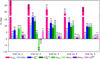 |
Fig. 4 Results of mass balance calculations of the trials. |
4.3 Reduction kinetics
For the determination of the reduction kinetics trial no. 2 is omitted because of its inaccurate mass balances. Besides variations of the reduction degree, namely the gained reduction degree
 (13)
(13)
and final reduction degree
 (14)
(14)
the oxygen removal rate rO is introduced to characterize the reduction [15]:
 (15)
(15)
Those values are shown in Figure 5. It is observed that trial no. 1 performs worse than no. 3 and 4. This is most likely due to its lower hydrogen flow rate. It seems that the scaling of the hydrogen flow rate with the reduction rate is roughly linear at the prevailing conditions, since a 36 % decrease in the former leads to a 41 % decline of the latter. However, this needs further investigation with more flow rate variations.
Trial no. 5 with the increased pre-reduction degree also features a lower reduction rate. This would indicate that the reduction gets slower progressively. While in principle this effect is expected, the reduction rate should only significantly start to decline at a reduction degree of 85 % as indicated by [15]. This would be more than twice the 40 % suggested by the pilot trials. However, it has to be noted that the basicity and the slag amount are very high in trial no. 5 due to the production method of the pre-reduced material. It was pre-reduced by HPSR for around 90 min, which means that the gangue gets concentrated when reducing the iron oxides. Therefore, while for the trials no. 3 and 4, the initial gangue content is 20 wt. % it is 31 wt. % for experiment no. 5, an increase of over 50 %. Furthermore, its starting basicity of 1.31 rises to 1.67 during the process, significantly higher than in the other trials.
In Figure 6, the equilibrium phase distribution as well as the total FeO activity aFeO of the final slags including possible precipitates are given varying with the temperature T. Those quantities are calculated with the software “FactSage 7.3” from “CRCT”, Montreal, Canada, and “GTT-Technologies”, Herzogenrath, Germany, using the databases “FToxid” and “FactPS (2019)” [23].
The initial expectation that, due to the increased gangue amount, the FeO activity would be too low for sufficient reduction kinetics is countered by the fact that for experiment no. 5 this parameter is either similar or even higher than in the two best trials. The main reason why the reduction was slower in trial no. 5 is therefore most likely the precipitation of solid magnesiowustite ((Mg,Fe)O) out of the liquid slag. At a temperature of 1600 °C, around 10 wt. % of the melt is solidified. Unfortunately, the dust generation was unusually high for this trial as soon as hydrogen was introduced into the plasma, which made the visual estimation of the solidified bath surface area impossible. Nevertheless, a certain amount of precipitated material was observed towards the edges of the crucible. Lastly, one more thing can be derived from the presented calculations: The comparatively high FeO activity after trial no. 1 supports the hypothesis that the hydrogen supply rate was the limiting factor for the reduction kinetics in this trial.
The average oxygen removal rate of the two best trials is 60 g/min. This means that the reaction kinetics needs to be increased 10-fold. This is required for the next planned upscaling step of processing 200 kg/h iron ore fines, which will include a pre-reduction unit [11]. However, the trials presented were not conducted under optimized conditions. Furthermore, the iron content of the used IBMs, around 57 wt. %, is low compared to ores typically used for reduction, which commonly consist of more than 65 wt. % Fe [24]. Higher oxygen removal rates have already been achieved at the pilot facility with other experiments, the results of which will be subject to follow-up publications.
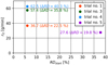 |
Fig. 5 Reduction kinetics. |
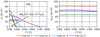 |
Fig. 6 Temperature dependence of the phase distribution and total FeO activities for the final slags. |
4.4 Comparison with laboratory HPSR plant
To allow for a fair comparison between a laboratory and pilot setup, ideally similar trials would be selected. However, no suitable experiments conducted at the laboratory HPSR plant located at the Technical University of Leoben are published. Nevertheless, the scaling of the HPSR process is still evaluated with the data available. For the laboratory reactor, oxygen removal rates are around 1 g/min at a batch-wise charged ore mass of 100 g [15]. This value is obtained for nealy full reduction of the ore. In contrast, the experiments representing the pilot plant (trials no. 3 and 4) were deliberately aborted after 90 min of reduction at reduction degrees just above 40 %. When assuming faster reduction kinetics at the beginning of the reduction [15], the stated performance metrics thus favor the pilot plant. However, as already mentioned, the pilot trials presented were not conducted under optimized conditions. While the amount of the charged IBM is 600 times larger at the pilot plant, the oxygen removal rate increased only 60-fold. This indicates that the upscaling might be highly non-linear. The reasons for this can be manifold and are the topic of further research. Possible explanations are the different geometric ratios and varying specific consumption figures. To further discuss this, it is first necessary to determine the density of the slag. This is done according to the method presented in [25].
For its calculation, an average composition of all input materials listed in Table 2 is assumed. Since the produced iron is liquid, the temperatures prevailing in the bath must be above its melting point of 1536 °C for pure Fe [26]. Therefore, the temperature is set to 1600 °C. Under these conditions, a density of around 3.4 t/m³ is estimated.
Utilizing the geometries given in [15] and Figure 1, this means the bath has a surface area of around 40 cm² at the laboratory setup and approximately 2000 cm² at the pilot plant, assuming the charge is fully molten. The corresponding bath heights are then roughly 1 cm and 10 cm, respectively. From these values, the ratios of the bath’s surface area to its volume are calculated to 0.1 mm²/mm³ for the small scale and 0.01 mm²/mm³ for the bigger one. This is a 10-fold decrease in specific surface area, having major implications on the mass and heat transfer characteristics of the melt. Moreover, this is evident when comparing the ratios of the applied electric power to the charged IBM masses. Those values are roughly 50 kW/kg in the laboratory and around 2 kW/kg at the pilot facility, translating to energy savings of 96 %. Since in [15] the applied power is not stated, 5 kW is used for this calculation since the facility is commonly operated at this level [4, 5]. The specific hydrogen input relative to the charged ore mass at the laboratory scale is around 500 Nl/kg, while approximately 900 Nl/kg is consumed at the pilot plant. This emphasizes the influence of the bath geometry and indicates that the ratio of the surface area to the bath height influences the reduction process significantly, as also stated by [7].
4.5 Upper vessel insulation concepts
Figure 7 shows the average power input, the distribution of the iron species and the gangue content in the slags for all conducted trials. A mean reduction in the necessary power input of around 25 % is obtained when applying insulation to the upper vessel (trials no. 3 to 5). Then, the reactor is operating at its maximum thermal limits. A further increase in power would lead to overheating the water-cooled steel pipe holding the cathode.
By comparing trials no. 1 to 4, the following observations can be made: Trials no. 3 and 4 show an increase in Fe₂O₃ content in their slags compared to trials no. 1 and 2. Additionally, the metallic iron and FeO concentrations in trials no. 3 and 4 are reduced. This can be attributed to the kinetically limited eutectoid phase transformation of FeO, as described previously in equation (12) [22]. The longer cooling times in the insulated setup facilitate greater decomposition of wustite.
According to this theory, it is anticipated that trials no. 1 and 2 contain less metallic iron in their slags than trials no. 3 and 4. However, the opposite effect was observed, which can be explained by more advantageous conditions for the coagulation of finely dispersed liquid metallic droplets in the insulated setups due to their extended residence times at higher temperatures during cooling. This leads to a better separation of the produced metal and the slag, counteracting the effect of the FeO decomposition.
However, the iron species distribution in the slag of trial no. 5 contradicts this theory of eutectoid phase transformation of FeO. An explanation is provided by the high gangue content of the last experiment: Those compounds stabilize the FeO, thereby significantly influencing the wustite decomposition [27].
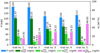 |
Fig. 7 Average electric power input, iron species distribution and gangue amount in the obtained slags. |
4.6 Crucible refractory materials
The wear of the refractory was the least in trial no. 4, which used phosphate-bonded magnesia material. Because of the variation in the values, the average is taken between trials no. 1 to 3 and no. 4 and 5 as representative for the magnesia-alumina spinel and the MgO-P material, respectively. Using the latter refractory could decrease the wear rate by around 35 %. From operational experience, even better refractory wear characteristics can be reported: While an MA spinel crucible needs to be relined usually after around four trials, the MgO-P lined vessel currently holds eight trials and is still suitable for further usage at the time of writing. The reason is most likely due to the formation of low-melting compounds when bringing the refractory in contact with the FeO-rich slag. This behavior is visualized in Figure 8. It shows the calculated solidus temperature Tsolid of the equilibrium of the two refractory materials mixed with variable amounts of FeO, representing the slag. Those calculations were done with the software “FactSage 7.3” using the databases “FToxid” and “FactPS (2019)”.
Above the stated temperatures liquid phases start forming, which aid in the wear of the refractory lining. This method indicates different levels of slag infiltration, since 0 wt. % FeO prevails within the refractory wall and 100 wt. % FeO is obtained within a pure FeO melt. For simplicity, the minor constituents in the MgO-P material mentioned previously are neglected. The refractories therefore consist only of Al2O3 and MgO with different ratios. While both lines decrease with increasing FeO content, the solidus temperature of the MA spinel starts at lower temperatures and decreases quicker. At 25 wt. % FeO in the mixture, the MgO-P material has a solidus temperature of 2240 °C, while the MA spinel already starts melting at 1415 °C. This can explain the increased wear rates of the latter. On the other hand, it is also possible that the binder between the grains gets dissolved faster than the grains themselves. This would then lead to whole grains breaking out. To understand the exact wear mechanism, further investigation is necessary.
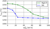 |
Fig. 8 Calculated solidus temperature for the investigated refractory systems in equilibrium with variable amounts of FeO. |
5 Conclusion
The results of five trials conducted at a pilot scale HPSR facility are presented. Different input materials, upper vessel insulation concepts and crucible refractory linings were investigated. The following main conclusions can be drawn from the experiments:
The experimental setup requires optimisation to achieve more accurate and consistent mass balances. This likely involves fully extracting the metal charged to protect the refractory at the crucible bottom after each trial. Additionally, slag sampling must be conducted in a more representative manner. The assumption that the slag is thoroughly mixed, meaning its analysed composition is independent of the sampling location, has been shown to be invalid, as evidenced by the results from trial no 2.
The dust discharge and refractory infiltration most likely need to be accounted for to further aid in more accurate mass balances.
Oxygen removal rates of around 60 g/min were achieved with non-optimized trials and low-grade input material. Since the reduction kinetics scaled roughly linearly with the hydrogen supply rate at the prevailing conditions, further improvements seem likely but require more extensive research. In fact, higher oxygen removal rates have already been achieved with other process parameters.
It is estimated that the bath’s surface area to height ratio influences the reduction significantly. However, this also needs a more in-depth investigation campaign.
MgO-P refractory material is recommended for all further experiments, since it is more resistant to the highly corrosive, FeO-rich slag than MA spinel.
Thermally insulating the upper vessel aids in obtaining more regularly shaped reguli. Furthermore, it provides better conditions for finely dispersed metallic droplets to coagulate, which improves the evaluation accuracy of the trial.
The thermal concept needs further improvement to operate with bigger input masses. A redesign of the cathode system is required to facilitate higher power input.
The conducted trials were explored to provide an overview of the operating principles and procedures at an experimental HPSR pilot facility. It is important to note that the trial parameters were not yet optimized. Further research suggests that higher reduction rates could be achievable. Follow-up studies, which will be detailed in future publications, have already observed faster reduction kinetics in multiple trials. However, additional investigative campaigns are essential to gain a deeper understanding of the process and its limiting factors. This knowledge will be crucial for designing the next scale-up step on the path toward demonstrating the industrial feasibility of the HPSR process.
Acknowledgments
The authors thank L. Gan for the fast response and for kindly providing the parameter a56 = 16.69 cm3 / mol required for the calculation of slag densities, which unfortunately was omitted in the original publication [25].
Funding
This research is part of the “Sustainable Steelmaking follow-up” project (no. 894616), funded by the Klima- und Energiefonds (www.klimafonds.gv.at, accessed on 25 July 2025) within the scope of the program “Vorzeigeregion Energie” through the Austrian Research Promotion Agency (www.ffg.at, accessed on 25 July 2025), K1-MET GmbH (www.k1-met.com, accessed on 25 July 2025), voestalpine Stahl GmbH (www.voestalpine.com/stahl/Gesellschaften/voestalpine-Stahl-GmbH, accessed on 25 July 2025), voestalpine Stahl Donawitz GmbH (www.voestalpine.com/stahldonawitz, accessed on 25 July 2025), Pirhofer-Automation e.U. (www.pirhofer-automation.at, accessed on 25 July 2025), the Chair of Ferrous Metallurgy at Technical University of Leoben (www.metallurgy.at/chair-of-ferrous-metallurgy, accessed on 25 July 2025), and WIVA P&G--Hydrogen Flagship Region Austria Power & Gas (www.wiva.at, accessed on 25 July 2025).
Conflicts of interest
The authors have no conflict of interest.
Data availability statement
Data associated with this article cannot be disclosed due to legal reasons.
Author contribution statement
Conceptualization, B.A. and M.A.Z.; Methodology, B.A.; Software, B.A.; Validation, B.A., M.A.F., J.S. and M.A.Z.; Formal Analysis, B.A.; Investigation, B.A. and M.A.F.; Resources, B.A. and M.A.Z.; Data Curation, B.A.; Writing – Original Draft Preparation, B.A.; Writing – Review & Editing, M.A.F., J.S., and M.A.Z.; Visualization, B.A.; Supervision, M.A.Z.; Project Administration, M.A.Z.; Funding Acquisition, M.A.Z.
References
- J. Somers, Technologies to decarbonise the EU steel industry, Joint Research Centre, European Commission, JRC127468, 2022 [Google Scholar]
- E. Bäck, K. Badr, J.F. Plaul et al., Überblick über die Entwicklung der Wasserstoff-Schmelzreduktion am Lehrstuhl für Metallurgie, BHM 154, 6–9 (2009) [Google Scholar]
- K. Badr, Smelting of Iron Oxides Using Hydrogen Based Plasmas. Dissertation, Montanuniversität Leoben, 2007 [Google Scholar]
- M.A. Zarl, D. Ernst, J. Cejka et al., A new methodological approach to the characterization of optimal charging rates at the hydrogen plasma smelting reduction process part 1: method, Materials 15, 4767 (2022) [Google Scholar]
- B. Adami, Untersuchung des Verhaltens von Phosphor, Schwefel und Kupfer während des Wasserstoffplasma-Schmelzreduktionsprozesses. Master's thesis, Montanuniversität Leoben, 2023 [Google Scholar]
- Y. Nakamura, M. Ito, H. Ishikawa, Reduction and dephosphorization of molten iron oxide with hydrogen-argon plasma, Plasma Chem. Plasma Process. 1, 149–160 (1981) [Google Scholar]
- P.R. Behera, B. Bhoi, R.K. Paramguru et al., Hydrogen plasma smelting reduction of Fe2O3, Metall. Mater. Trans. B 50, 262–270 (2019) [Google Scholar]
- I.R. Souza Filho, Y. Ma, M. Kulse et al., Sustainable steel through hydrogen plasma reduction of iron ore: process, kinetics, microstructure, chemistry, Acta Materialia 213, 116971 (2021) [Google Scholar]
- B. Hakim, M. Akbar Rhamdhani, T. Hidayat et al., Fast iron production from limonite iron ore in a lab-scale hydrogen plasma smelting reduction (HPSR) reactor, J. Sustain. Metall. (2025). [Google Scholar]
- F. Hoffelner, M.A. Zarl, J. Schenk, Development of a new laboratory-scale reduction facility for the hydrogen plasma smelting reduction of iron ore based on a multi-electrode arc furnace concept, IOP Conf. Ser.: Mater. Sci. Eng. 1309, 012012 (2024) [Google Scholar]
- B. Adami, F. Hoffelner, M.A. Zarl et al., Strategic selection of a pre-reduction reactor for increased hydrogen utilization in hydrogen plasma smelting reduction, Processes 13, 420 (2025) [Google Scholar]
- M.A. Zarl, M.A. Farkas, J. Schenk, A study on the stability fields of arc plasma in the HPSR process, Metals 10, 1394 (2020) [Google Scholar]
- J.F. Plaul, W. Krieger, E. Bäck, Reduction of fine ores in argon-hydrogen plasma, Steel Res. Int. 76, 548–554 (2005) [Google Scholar]
- L. Stiny, Grundwissen Elektrotechnik und Elektronik: Eine leicht verständliche Einführung, Springer Fachmedien, Wiesbaden, Germany, 2018 [Google Scholar]
- D. Ernst, U. Manzoor, I.R. Souza Filho et al., Impact of iron ore pre-reduction degree on the hydrogen plasma smelting reduction process, Metals 13, 558 (2023) [Google Scholar]
- M. Tanaka, S. Tashiro, T. Satoh et al., Influence of shielding gas composition on arc properties in TIG welding, Sci. Technol. Weld. Joi. 13, 225–231 (2008) [Google Scholar]
- E.T. Turkdogan, Fundamentals of steelmaking, The Institute of Materials, London, UK, 1996 [Google Scholar]
- P. Linstrom, NIST Chemistry WebBook, NIST Standard Reference Database 69, National Institute of Standards and Technology, 1997 [Google Scholar]
- P. Cavaliere, Clean ironmaking and steelmaking processes: efficient technologies for greenhouse emissions abatement, Springer Nature, Cham, Switzerland, 2019 [Google Scholar]
- M. Hasegawa, Ellingham Diagram, Treatise Process Metall.: Process Fundamentals, 507–516 (2014). [Google Scholar]
- R.A. Lanzmaier, Methodenentwicklung zur Staubcharakterisierung beim Wasserstoffplasma-Schmelzreduktionsprozess, Master's thesis, Montanuniversität Leoben, 2024 [Google Scholar]
- S. Hayashi, S. Yoneda, Y. Kondo et al., Phase transformation of thermally grown FeO formed on high-purity fe at low oxygen potential, Oxid. Met. 94, 81–93 (2020) [Google Scholar]
- Centre for Research in Computational Thermochemistry, GTT Technologies, FactSage Software and Databases, https://www.factsage.com, accessed on 08.07.2025 [Google Scholar]
- J. Legemza, R. Findorák, M. Fröhlichová et al., Advances in sintering of iron ores and concentrates, Iron Ores (2021). [Google Scholar]
- J. Xin, L. Gan, N. Wang et al., Accurate density calculation for molten slags in SiO2-Al2O3-CaO-MgO-‘FeO’-‘Fe2O3’ systems, Metall. Mater. Trans. B 50, 2828–2842 (2019) [Google Scholar]
- M. Degner, R. Fandrich, G. Endemann et al., Stahlfibel, Verlag Stahleisen, Düsseldorf, Germany, 2011 [Google Scholar]
- A. Vignes, Extractive metallurgy 1: basic thermodynamics and kinetics, ISTE, London, UK, 2011 [Google Scholar]
Cite this article as: Bernhard Adami, Manuel A. Farkas, Johannes Schenk, Michael A. Zarl, Advancing hydrogen plasma smelting reduction: Experimental insights from a pilot plant, Matériaux & Techniques 114, 105 (2026), https://doi.org/10.1051/mattech/2025029
All Tables
All Figures
|
Fig. 1 (A) Schematic cross section (all dimensions in mm) and (B) photograph of the HPSR pilot plant. |
| In the text | |
|
Fig. 2 Visual insights into trial no. 4: (A) before ignition, (B) and (C) during pre-melting, (D) and (E) during reduction, (F) during controlled process ending. |
| In the text | |
|
Fig. 3 Photographs of (A) the crucible contents before breaking out, (B) a sample of the slag above the regulus, (C) the metallic regulus and (D) a sample of the slag below the regulus for trial no. 4. |
| In the text | |
|
Fig. 4 Results of mass balance calculations of the trials. |
| In the text | |
|
Fig. 5 Reduction kinetics. |
| In the text | |
|
Fig. 6 Temperature dependence of the phase distribution and total FeO activities for the final slags. |
| In the text | |
|
Fig. 7 Average electric power input, iron species distribution and gangue amount in the obtained slags. |
| In the text | |
|
Fig. 8 Calculated solidus temperature for the investigated refractory systems in equilibrium with variable amounts of FeO. |
| In the text | |
Current usage metrics show cumulative count of Article Views (full-text article views including HTML views, PDF and ePub downloads, according to the available data) and Abstracts Views on Vision4Press platform.
Data correspond to usage on the plateform after 2015. The current usage metrics is available 48-96 hours after online publication and is updated daily on week days.
Initial download of the metrics may take a while.