")
")
| Issue |
Matériaux & Techniques
Volume 111, Number 1, 2023
|
|
|---|---|---|
| Article Number | 103 | |
| Number of page(s) | 16 | |
| Section | Materials production and processing | |
| DOI | https://doi.org/10.1051/mattech/2023013 | |
| Published online | 29 mai 2023 | |
Review
Effect of powder reuse on physical, chemical and toxicological properties of 6061-Zr aluminum alloy processed by Laser Powder Bed Fusion (L-PBF)☆
Effet de la réutilisation de la poudre sur les propriétés physiques, chimiques et toxicologiques de l’alliage d’aluminium 6061-Zr produit par fusion laser sur lit de poudre (L-PBF)
1
Université de Lyon, École Centrale de Lyon – École Nationale d’Ingénieurs de Saint-Étienne, Laboratoire de Tribologie et Dynamique de Systèmes, CNRS UMR 5513, 58 rue Jean Parot, 42023 Saint-Étienne, France
2
École des Mines de Saint-Étienne, EMSE Centre Ingénierie et Santé – Département Activité biologique des Particules Inhalées, UMR INSERM U1059, Saint-Étienne, France
3
Institut National de Recherche et de Sécurité, Centre de Lorraine, rue du Morvan, CS 60027, 54519 Vandœuvre-lès-Nancy Cedex, France
* e-mail: Cette adresse e-mail est protégée contre les robots spammeurs. Vous devez activer le JavaScript pour la visualiser.
Received:
21
November
2022
Accepted:
16
April
2023
Abstract
Laser Powder Bed Fusion (L-PBF) is an additive manufacturing process, which allows to produce metallic parts layer by layer. The reuse of the powder is critical for cost part. The reuse can modify the powder and thus the printed parts properties. This study is focused on a severe reuse of 6061-Zr by analyzing the physico-chemical features of the powder, their impact on both the printed parts and toxicological properties. The results of this study showed a high physico-chemical stability of 6061-Zr powder under severe reuse even if oxygen content increase on the reused powder. This study highlights the high amount of oxygen and the variation in chemical composition of the sieving residue. Besides, the toxicological properties of the powder and the mechanical features of the printed parts are unchanged. These results show that in addition to guaranteeing a specific particle size, sieving limits the oxygen increase and the chemical modification of the powder.
Résumé
La fusion laser sur lit de poudre (L-PBF) est un procédé de fabrication additive qui permet de produire des pièces métalliques couche par couche. La réutilisation de la poudre est critique pour le coût de la pièce. La réutilisation peut modifier la poudre et donc les propriétés des pièces imprimées. Cette étude se concentre sur une réutilisation sévère de 6061-Zr en analysant les caractéristiques physico-chimiques de la poudre, leur impact sur les pièces imprimées et les propriétés toxicologiques. Les résultats de cette étude ont montré une grande stabilité physico-chimique de la poudre 6061-Zr dans le cadre d’une réutilisation sévère, même si la teneur en oxygène augmente dans la poudre réutilisée. Cette étude met en évidence la quantité élevée d’oxygène et la variation de la composition chimique du résidu de tamisage. En revanche, les propriétés toxicologiques de la poudre et les caractéristiques mécaniques des pièces imprimées restent inchangées. Ces résultats montrent qu’en plus de garantir une granulométrie spécifique, le tamisage limite l’augmentation de l’oxygène et la modification chimique de la poudre.
Key words: additive manufacturing / aluminium alloy / Laser Powder Bed Fusion (L-PBF) / Selective Laser Melting (SLM) / powder reuse / recycling
Mots clés : fabrication additive / alliage d’aluminium / fusion laser sur lit de poudre (L-PBF) / fusion sélective par laser (SLM) / réutilisation des poudres / recyclage
This article is based on a contribution (and published after peer-review and revision) presented in the Laserap workshop (10–14/10/2022, Semur-en-Auxois, France).
© M. Beal et al., 2023
 This is an Open Access article distributed under the terms of the Creative Commons Attribution License (https://creativecommons.org/licenses/by/4.0), which permits unrestricted use, distribution, and reproduction in any medium, provided the original work is properly cited.
1 Introduction
Laser Powder Bed Fusion (L-PBF), also known as Selective Laser Melting (SLM), is a technology that produces near net shape metallic three-dimensional (3D) parts layer by layer [1]. The raw material used is a powder that is layered before being locally fused by a laser. Many studies have been published in the literature concerning the optimization of the main process parameters (laser power, scan speed, hatch distance) and efficient laser strategies. Various common alloys are used for metal additive manufacturing, including Ti6Al4V, Inconel 718, stainless steel 316 L, stainless steel 304 L, and aluminium alloys such as AlSi10Mg [2]. Some materials are very difficult to process by L-PBF and their chemical compositions needs some element additions to meet the properties required by additive manufacturing processes. This is the case of the 6061 aluminium alloy, which exhibits hot crack failures by L-PBF. So, it has been modified by zirconium addition (Patent FR 3 075 828 – A1). As the L-PBF technology becomes mature, issues related to industrial use are emerging, especially the reuse of the powder. Indeed, material costs can represent up to 31% of the additive manufacturing process cost [3]. Thus, the reuse of metal powder has significant economic benefits for users of this technology, 92% reduction on material cost was found if the powder was reused 15 times [2]. In addition to the financial aspect, the reuse of the powder also represents an environmental benefit. According to Smith [4] and Petrovic et al. [5] between 90% and 98% of the unfused powder can be recovered and reused. However, this result is highly dependent on the type of machine used, the type of parts printed and the cleaning methods.
Due to the L-PBF process, the reused powder contains some particles partially or completely melted, some thermally affected particles and some spatters (particles created by ejections from the melt pool). This led to size and shape modifications of particles or/and to oxygen pick up. These modifications at the particle scale can modify the toxicity of the powder as well as the properties of the built parts. The reused powder characteristics must be as close as possible to those of the virgin powder initially produced by the supplier.
Studies on the reuse of powders have been carried out, it seems that the results in the literature vary greatly from one study to another, and all things considered, a poor extrapolation to a new alloy such as 6061-Zr is possible. This variability mainly depends on the alloys used, but also on the 3D printing machine, the type of production including their duration and their time spacing. For example, some authors showed that the particle size was constant [6–8], others that the particle size increased [9–11] while Del Re et al. showed a particle size decrease after reusing the powder [12]. It is possible to find this dispersion of results for other properties concerning both powders and printed parts. Some powder reuse studies also include a step of introducing virgin powder before each printing which can impact the result. Finally, the reusability of a powder depends strongly on the specifications defined by each end-users (chemical composition of the built parts for example). Concerning health aspects, aluminium is not classified as a carcinogenic [ICSC:0988, November 2019]. However, effects of aluminium use in the industry have been reported. Particularly in additive manufacturing, people are exposed to fine aluminium powders. In fact, intensive and repeated exposure during the transformation of alumina into aluminium or during the industrial use of aluminium powders causes pneumoconiosis (aluminosis), a respiratory disease due to the inhalation and fixation in the lung of metallic aluminium dust [13].
The aim of this study is to establish the assessment of the reuse of aluminium alloy 6061 powder modified by the addition of Zirconium in an industrial context. Based on three strong axes, the physicochemical properties of the powder (granulometry, morphology, oxygen content, moisture content, chemical composition), the toxicological properties of the powder (cytotoxicity and pro-inflammatory response) as well as the L-PBF processing such as printed parts (density, roughness, mechanical properties) and powder bed properties. Indeed, this study allows to determine if the reuse leads to modification of the powder, which results in mechanical and/or health issues.
2 Material and methods
2.1 Material and L-PBF equipment
The powder used in this study is an aluminium alloy 6061 with added Zirconium developed and patented by Thales (Thales, Valence, France). This powder was produced by gas atomization and the particle size distribution is between 5 and 65 μm. The 6061 alloy is a heat treatable aluminium alloy based mainly on silicon (Si) and Magnesium (Mg). However, its Si content (0.4–0.8 wt%) is much lower than cast aluminium alloys such as AlSi12, AlSi10 and AlSi7, which show excellent printability. In fact, for AlSi10Mg, the silicon content is near eutectic composition, which makes good melt pool fluidity and very low shrinkage. On the other side, the low silicon content confer attractive properties to 6061 alloy such as a good ratio mechanical properties/density, a high corrosion resistance, an ability for hard anodizing and a good thermal conductivity [14]. So, this alloy is commonly used in the aircraft, aerospace and automotive industries. However, the 6061 alloy is rarely used in L-PBF because of high sensitivity to hot cracking during solidification (phenomenon already investigated in welding [15,16]). Several aspects are exposed as the main phenomena responsible of hot cracking [17]: (i) the difference between the solidus and liquidus temperatures, (ii) the difficulty of the liquid material to get to the shrinkage zones due to the columnar dendritic network of the mushy zone. This phenomenon is emphasized by the high solidification rate during L-PBF process. The addition of Zirconium is a way to avoid the problem of hot cracking that 6000 and 7000 aluminium alloys series show. In fact, the addition of Zr reduces the melt pool viscosity and induces the precipitation of fine particles Al3Zr, which act as nucleation sites producing thin and equiaxed grains specially at the melt pool boundaries [17–19].
This powder was printed on a 3DSystems ProX200 L-PBF machine. The size of the building plate of this machine is 140 × 140 mm. The superposition of the metal powder layers is done by a roller. Excess metal powder during spreading is collected in a “used powder container”. The maximum theoretical laser power is 300 W with a 150 μm laser beam diameter. The printing parameters used for 6061-Zr are: laser power = 300 W, scan speed = 2200 mm/s, recovery rate = 50% (hatch distance = 70 μm), layer thickness = 30 μm and atmosphere gas = argon.
2.2 Methods of characterization
2.2.1 Physical and chemical characterization of powders
The morphology of the particles as well as the granulometry are analyzed with a morpho-granulometer (Occhio®-500NANO XY). Three samples (of ∼ 50 000 particles) are analyzed per batch. The granulometry of the particles will be expressed via the equivalent diameter (Deq, Eq. (1)), where A [μm2] is the area of the projected particle.
 (1)
(1)
The analysis of morphology will be based on the sphericity criterion named roundness (Rn, Eq. (2)) with Deq [μm] the equivalent diameter and xFmax [μm] the maximum Feret diameter of the particle.
 (2)
(2)
The microscopic observations of virgin and reused powders are performed on a scanning electron microscope (SEM, TESCAN Vega II SBH).
The study concerning the layering phase consists firstly in comparing the granulometry and the morphology of the particles layered on the building plate to those present in the feeding piston called “free powder”.
The density of the layering is also studied. Indeed, the granulometry as well as the morphology can influence the density of the powder bed. Figure 1 shows the different cycles undergone by the gourds during the process, allowing to analyze the powder bed. Once the process is complete, the gourds are removed from the plate and weighed. The gourds are then emptied of their powder and the empty mass is measured. The delta of the mass corresponds to the mass of powder present in the bottle. This value is divided by the theoretical volume of the gourds to obtain the density of the powder bed.
The moisture analysis between virgin and reused powder is carried out by the loss of mass (evaporation), measured with a Simultaneous Symmetrical Thermo Analyser (setaram®-TAG). The specific surface of the powder is obtained by BET analysis (Mastersizer, Hydro 2000S) using krypton gas (Kr, normal liquefaction, degassing temperature at 77.35 K). Oxygen content is obtained by Inert Gas Fusion (Leco® TC-436). The chemical elements analysis is done by Inductively Coupled Plasma – Atomic Emission Spectroscopy (ICP-AES).
 |
Fig. 1 Schematic illustration of gourds concept to analyze the powder layered during L-PBF process: (a) the roller spread the new layer; (b) the layer is spread and ready to be melted; (c) the laser solidify the contour (the gourd) to imprison the layered powder; (d) the gourd is ready for the next layer; (e) finished gourd ready to be analyzed. Illustration schématique du concept de gourde pour analyser la couche de poudre pendant le processus L-PBF : (a) le rouleau étale la nouvelle couche ; (b) la couche est étalée et prête à être fondue ; (c) le laser solidifie le contour (de la gourde) pour emprisonner la couche de poudre ; (d) la gourde est prête pour la couche suivante ; (e) la gourde finie prête à être analysée. |
2.2.2 Cellular toxicological characterization of powders
The objective of these tests is to observe the evolution of the cytotoxicity (i.e. the degree to which aluminium particles cause damage to a cell) and inflammatory response of the aluminium powder during its reuses in L-PBF process. For that, in vitro toxicological tests were used on a macrophage cell line. Macrophages are effector cells of the innate immune system that phagocytose bacteria and release pro-inflammatory and antimicrobial mediators. These cells were incubated with aluminium particles for 24 h in a biological environment at 37 °C under 5% CO2.
In a first step, the measurement of the level of cytotoxicity is obtained by measuring the LDH (Lactal Desydogenas), which is released during the destruction of the cell membrane. The extracellular release of LDH is used to monitor the loss of integrity of the cell membrane (e.g. alteration of the plasma membrane by a toxic agent). The extracellular release of LDH is therefore an indirect measure to quantify the cytotoxicity of particles.
In a second step, the level of inflammation, due to the effect of the exposure of the cells to the aluminium powder, is determined by measuring the cytokine TNF-α (Tumor Necrosis Factor alpha). TNF-α is a protein secreted by macrophage cells that is involved in the inflammatory process and immune responses. TNF-α present in the supernatant is quantified after approximately 24 h of incubation between cells and aluminium particles with an enzyme-linked Immunosorbent Assay.
The tests were performed in a triplicate configuration (3 reproductions on each replicate, for 4 exposure doses, from 15 to 120 μg powder/ml).
2.2.3 Characterization of printed parts
The density of samples is obtained by images analysis (optical density). To reinforce the density results significance, the density variation of the printed parts is also measured by pycnometer (Quantachrome® – Ultrapyc 1200). The measurement allows to obtain the mass [g] and the volume [cm3] of samples conducting to the real density [g/cm3]. For each studied cycle, four cylinders of 21 mm diameter and 10 mm height are analyzed. Concerning the image analysis, the samples were polished and analyzed on an optical microscope, the magnification is x5 and the total analyzed surface is 200 mm2 per sample. The processing is done on ImageJ (Java-based image processing program).
Regarding the roughness, the Sa [μm] (arithmetic mean height) values were analyzed on the top surface and one of the lateral surfaces of the resilience samples. These roughness measurements were carried out with a focus variation microscope (Alicona®-InfiniteFocus) at x5 magnification.
The Ultimate Tensile Strength (UTS [MPa]), the yield strength (Rp0.2 [MPa]) and the elongation at break (A [%]) are measured by tensile tests according to ISO6892 (on machined samples). The resilience is determined according to ISO 148-1:2016 with V grooves (on as build samples).
In order to avoid as much as possible, the deposition of aggregates from the parts being lasered on the parts soon to be lasered, the order of lasering has been optimized. This consists in being in the opposite direction of the protective argon flow (the first part lasered is located opposite the gas nozzle and the last part is the closest to this nozzle).
2.3 Powder reuse methodology and printing sequences
The powder reuse cycle consists of filling the feed piston of the machine (≈ 4000 cm3), printing with this powder and recycling it without adding virgin powder contrary to industrial method where virgin powder is added before a new build. Each company has internally developed the ratio between virgin and used powder to ensure good properties to their printed parts. Nevertheless, it seems that very little communication is done by the companies on this subject. Moreover, the addition of virgin powder makes the observation of the variations more complicated. The objective of the study is to observe the changes related to the reuse of the powder to then understand which actions are to be set up to guarantee the properties of the printed parts. This is the reason why no addition of virgin powder is done in this study to isolate the effect of reuse on a defined population.
In order to avoid dissociating as much as possible the problems of aging of the metal powder from those of its reuse, the study of reuse was carried out within a restricted period of 10 days. Between each print, the powder is sieved with an ultrasonic sieve with a 63 μm mesh. The objective of this study is to characterize the reuse in a simple industrial case study. Therefore, the powder is sieved in air and is neither dried nor mixed. As soon as the powder is loaded in the machine, the characterization plate is printed. This plate contains 8 tensile specimens, 3 resilience specimens, 4 cylinders for the density of the printed parts and 2 gourds for the density of the powder bed. As previously mentioned, the objective is to reproduce the reuse during an industrial production in a simple way: loaded plates, without drying, without inert protective atmosphere. Our objective is to simulate the pollution generated by the thermally affected particles and the spatters during part production. A simplifying reasoning based on the direct relation between the external surface of the part and the quantity of polluted powder has been retained and illustrated below in Figure 2. This figure shows the surface of the polluted powder bed at a layer n. The reasoning used allows us to say that this area is related to the perimeter of the part (part/powder bed contact). This reasoning extended to all layers relates the volume of polluted powder to the external surface of printed parts.
This reasoning allows assuming that a characterization build with the same external surface as an industrial parts build will pollute the powder in a similar way. An industrial production of aeronautical parts has been analyzed. The ratio “external surface [mm2]”/“print height [mm]” of the industrial build is near 2600 mm2/mm and has been reproduced in the laboratory study.
Once the machine is loaded (Fig. 3a) and the characterization plate printed (Fig. 3b), a quantity of powder remains available in the feed piston. Fins were printed afterwards to pollute the remaining powder as shown in Figure 3c.
This part shape (fins) was chosen because it has a high external surface compared to the amount of sintered powder. The number of fins was set at 26 to minimize the difference of the ratio “external surface [mm2]”/“print height [mm]” of the industrial plate, the characterization plate and the fin plate to pollute the powder bed in a same way. The ratio differences are less than 1%. The fins are 50 mm long and 1.5 mm wide. Since the fins plates are used to pollute the remaining powder, the height of these plates decreases with each reuse, as shown in Figure 4, related to the decrease of the amount of powder available after each cycles.
Figure 5 summarizes the steps employed in the 6061-Zr aluminium powder reuse study. The powder will be reused 6 times in this study. This number is low compared to a study where virgin powder would be added to each cycle [6]. However, the “extreme” conditions of the reuse, the highly loaded trays and the fact that the same powder is used throughout the reuses allow us to conclude if the powder can be reused. In the conditions of this study, if the powder keeps its properties and consequently those of the printed parts, the addition of virgin powder at each cycle will only improve the quality of the powder and consequently guarantee the good construction of the parts.
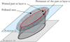 |
Fig. 2 Schematic illustration of pollution mechanism during L-PBF. Illustration schématique du mécanisme de pollution pendant le procédé L-PBF. |
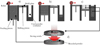 |
Fig. 3 Print sequence during reuse study: (a) powder loading; (b) characterization plate print; (c) fins print to use the powder still in the feeding piston; (d) sieving process to recycle the powder in order to reuse it for the next print. Séquences d’impression pendant l’étude de réutilisation : (a) chargement de la poudre ; (b) impression du plateau de caractérisation ; (c) impression des ailettes pour utiliser la poudre encore présente dans le piston d’alimentation ; (d) processus de tamisage pour recycler la poudre afin de la réutiliser pour l’impression suivante. |
 |
Fig. 4 Fins prints after (a) 0 reuse, (b) 1 reuse and (c) 2 reuse of powder. Impressions des ailettes après (a) 0 réutilisation, (b) 1 réutilisation et (c) 2 réutilisations de la poudre. |
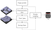 |
Fig. 5 Diagram of powder reuse steps. Diagramme des étapes de réutilisation de la poudre. |
3 Results and discussion
3.1 Modification of the physico-chemical properties of the reused powder
3.1.1 Morphology and granulometry of particles
The morphology and the granulometry of the metal powder are two essential properties, as they strongly influence the L-PBF process [7]. The evolution of the D10, D50 and D90 of the powder for each of the 6 reuse cycles are shown in Figure 6.
No significant changes in powder size were observed. However, this size stability is not always observed in the literature. Indeed, some studies of the reuse of metal powders show the decrease of the granulometry [12], others, a size stability [6,8] and some studies a size increase [9–11,20]. The possible size change seems to be highly dependent on the initial particle size of the virgin metal powder, the sieving method used as well as the cleaning method of the machine between two prints. In our case, as much powder as possible was collected and reused between each cycle, i.e. the excess powder present in the “used powder container”, the powder not fused on the build plate, the powder fallen on the edges of the piston during the layering process, the powder on the walls of the build chamber (spatters/fumes).
The SEM (Scanning Electron Microscopy) pictures show that the virgin powder is quite heterogeneous in granulometry and morphology (Fig. 7). The presence of two main populations was observed: spherical particles with a diameter of less than 15 μm as represented in Figure 7a as well as larger particles with a diameter near 50 μm, also spherical, represented in Figure 7b. Nevertheless, in addition to these particles, the presence of aggregates (Fig. 7d), porous particles (Fig. 7c) and particles with “satellites” is clearly observed. After 6 reuses of the metal powder, the heterogeneity is still present, however, the appearance of deformed particles (Fig. 7e) and coarse aggregate particles (Figs. 7f and 7g), which have been thermally affected, is doubtless noticed. The particles collected in the sieve residue are coarser (diameter > 63 μm, 63 μm corresponding to the cut-off of the sieve), some are crinkled and have “satellites” (Fig. 7g), others are perfectly spherical (Fig. 7h).
The graphs in Figure 8 compare the morpho-granulometry of the virgin powder, the 6-time reused powder and the sieve residue. As discussed previously, the particle size between the virgin and 6-times reused powder does not vary. However, it is interesting to see that the sieve cuts the powder granulometry relatively well at 63 μm. It is also interesting to note that the roundness of the sieve residue is better than that of the virgin powder. No significant change of the roundness is observed between virgin and reused powder. However, it should be noted that the roundness of the virgin powder is mediocre. It is therefore more difficult to see a decline of this factor contrary to other studies where the roundness in the initial state is much better [10,11]. As previously illustrated in the SEM images (Fig. 7h), some particles from the sieve residue are perfectly spherical. They are probably ejections of molten particles from the melt pool, which have time to solidify before touching other particles or the machine walls.
The specific surface of the powder was measured and this too does not change with reuse. The specific surface of the virgin powder is relatively high, due to the presence of fine particles, however it does not increase with reuse. This non-increase is probably favorable to avoid the accentuation of moisture adsorption. Indeed, we assume that the lower the specific surface is, the less contact there is between the powder and the environment (Fig. 9).
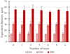 |
Fig. 6 Equivalent diameter for each reuse cycle. Diamètre équivalent pour chaque cycle de réutilisation. |
 |
Fig. 7 SEM images from virgin powder, 6x used powder and residual powder from sieving: (a) small round virgin particle; (b) big round virgin particle; (c) porous particle; (d) aggregates; (e) deformed particle; (f) coarse aggregate particle (Deq < 63 μm); (g) coarse aggregate with satellites (Deq > 63 μm); (h) big round particle thermally affected (Deq > 63 μm). Images MEB de la poudre vierge, de la poudre utilisée 6x et de la poudre résiduelle après le tamisage : (a) petite particule ronde vierge ; (b) grosse particule ronde vierge ; (c) particule poreuse ; (d) agrégats ; (e) particule déformée ; (f) particule agrégée grossière (Deq < 63 µm) ; (g) agrégat grossier avec satellites (Deq > 63 µm) ; (h) grosse particule ronde affectée thermiquement (Deq > 63 µm). |
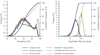 |
Fig. 8 Roundness and equivalent diameter of virgin powder, 6 times reused powder and sieving residue. Circularité et diamètre équivalent de la poudre vierge, de la poudre réutilisée 6 fois et du résidu de tamisage. |
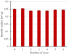 |
Fig. 9 Specific surface area for each reuse cycle. Surface spécifique pour chaque cycle de réutilisation. |
3.1.2 Powder bed
The particle size within the gourds (layering study) does not change over the reuse cycles (Fig. 10). This is in agreement with the stability observed for the particle size of the “free” powder. Nevertheless, it can be observed that the particle size of the layered powder presented in Figure 10 is smaller than the particle size of the free powder. By averaging the values over the cycles, the D10 decreases from 14 μm to 13 μm, the D50 from 30 μm to 26 μm and the D90 from 55 μm to 48 μm. This difference is mainly related to the 30 μm layering height because the space between the roller and the previous layer is too small for the biggest particles. However, the D90 is still 1.5 times larger than the layering height. Three phenomena seem to be mainly responsible for this gap between the granulometry present in the layer and the layer thickness. The first one concerns the layering on the lasered surfaces. The theoretical layer is 30 μm however a retraction appears following the lasering of the layer because the powder bed is not 100% dense contrary to the melt pool. The second one concerns the gourds concept; if we consider that the compaction of the powder bed is insufficient, the particles can still move and arrange themselves after several layers contrary to the layering above build parts. This allows particles with a diameter greater than the coating height to be in the powder bed. The third assumed phenomenon concerns the non-perfect sphericity of the particles, which allows them to pass under the roller in one direction despite the calculated equivalent diameter, which is greater than 30 μm.
The SEM images (Fig. 11) show that the thermally affected and deformed particles are present in the gourds from cycle 0 (virgin powder). However, it has been shown previously in the analysis of the “free” powder that as the reuse of the powder progresses, this type of particle appears in the population. Their number can be higher when the powder is used several times. However, these particles are part of the process and are not directly dependent on the reuse of the powder. Their presence is unavoidable and it can be assumed that their impact on the process is not detrimental as long as their number remains reasonable and they are uniformly dispersed in the powder bed.
Figure 12 shows the stability of the powder bed density over reuse. This is also in agreement with the stability of the powder morpho-granulometry discussed earlier. The density of the powder bed is slightly less than 50% apart for the last print with 51%.
 |
Fig. 10 Particle size of powder bed for each reuse cycle. Taille des particules du lit de poudre pour chaque cycle de réutilisation. |
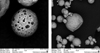 |
Fig. 11 SEM pictures of thermally affected powder in powder bed after first use. Images SEM de la poudre affectée thermiquement dans le lit de poudre après la première utilisation. |
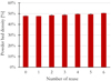 |
Fig. 12 Powder bed density for each reuse cycle. Densité du lit de poudre pour chaque cycle de réutilisation. |
3.1.3 Oxygen content
The oxygen content in the powder increases significantly from ≈ 2600 ppm to ≈ 3000 ppm after 6 cycles of reuse. A reuse-related increase in oxygen was also found by Rock et al. [20], Yu Sun et al. [11] as well as Laura Cordova et al. [10]. This increase in oxygen is mainly due to the absorption of oxygen by the melt pool projections [6]. The oxygen content of the particles presents in the sieving residue is ≈ 4800 ppm. The sieving process controls the particle size but also limits the evolution of the overall oxygen content. Indeed, the majority of powders with diameters greater than 63 μm were thermally affected or projected from the melt pool (Fig. 13).
We can observe in Figure 14a that some dark spots are present on the surface of thermally affected particles (spatters). An EDS mapping allowed us to determine that these spots are rich in oxygen (Fig. 14b). A similar finding has been put forward by Marco Simonelli et al. [21].
A second mapping was performed to analyze the other elements. This measurement has been done on a particle with less spots and focused on the median part of this particle. The objective was to observe the elements present in these spots. We can see that the observed spot is poor in Zr, Si and Cu but seems rich in Mg. We suppose that the oxide formed on the surface of this particle is an oxide of Mg and/or Al (Fig. 15).
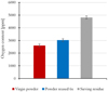 |
Fig. 13 Oxygen content of virgin powder, 6 times reused powder and sieving residue. Teneur en oxygène de la poudre vierge, de la poudre réutilisée 6 fois et du résidu de tamisage. |
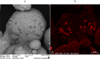 |
Fig. 14 (a) SEM pictures of thermally affected powder and (b) EDS analysis of oxygen. (a) Images MEB de la poudre affectée thermiquement et (b) analyse par EDS de l’oxygène. |
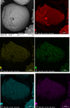 |
Fig. 15 SEM pictures of thermally affected powder and EDS analysis. Images MEB de la poudre affectée thermiquement et analyses EDS. |
3.1.4 Moisture content
The mass loss between the virgin powder and the 6 times reused powder is similar. The amount of moisture present in the reused powder is similar to the virgin powder. It can also be seen that 90% of the mass loss occurs in 1 h and 30 minutes. Nevertheless, the mass loss kinetics is probably related to the low mass of powder employed for this type of analysis (≈ 1.5 g). This kinetics may not be valid for the drying of bigger volumes (Fig. 16).
This result is very interesting because the reuse cycles of the powder were carried out in only 10 days to avoid its ageing and in particular the increase of the adsorbed moisture rate. Aluminium alloys are very sensitive to moisture adsorption. This increase in moisture content in the powder can cause the increased presence of small spherical pores caused by the formation of hydroxide [22–25].
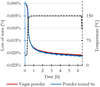 |
Fig. 16 Mass loss of virgin powder and reused powder. Perte de masse de la poudre vierge et de la poudre réutilisée. |
3.1.5 Elemental chemical composition
Chemical analysis was performed on the powder reused one time and on the sieve residue. Figure 17 shows that the chemical composition ratios do not vary significantly between the virgin and reused powder. This result is coherent since the majority of the powder that passes through the sieve during sieving was not thermally affected. However, it is interesting to observe that the chemical composition ratio varies for the sieving residue. This variation can be observed on the Mg/Zr and Cu/Mg ratios. For the sieving residue, the Mg/Zr ratio is lower and the Cu/Mg ratio is higher than for the virgin powder. A loss of Mg is thus observed. This illustrates that the majority of the particles that do not pass the 63 μm sieve have been sufficiently thermally affected to show a loss of Mg. This phenomenon is known during the SLM process for aluminium alloys such as 6000 series and 7000 series (Mg and Zn evaporation) [26].
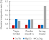 |
Fig. 17 Evolution of the elemental chemical composition of the powder. Évolution de la composition chimique de la poudre. |
3.1.6 Impact of reusing powder on cytotoxicity and pro-inflammatory response
Figure 18 show the LDH released during different tests for aluminium powder concentration from 15 to 120 μg/mL. To calibrate the tests, we used C− and C+ samples. The C− (negative control) is the level of LDH, which corresponds to a test where the cells are not in contact with aluminium powder. The C+ (positive control) is a measure of LDH where all cells are damaged by a lysing agent. According to these results (Fig. 18) we can conclude that regardless of the exposure dose and the type of aluminium powder (virgin or reused), the results show the same level as the C− (negative control). This means that there is no statistically significant effect of aluminium powder on cytotoxicity.
In Figure 19, according to the level of the C− (negative control, i.e. experimental condition where the cells are not in contact with aluminium powder), we can see that there is no significant effect of virgin and reused aluminium powder on the pro-inflammatory reaction.
These results do not indicate that virgin and reused powder is safe, particularly for chronic exposure at low doses over many years or decades of exposure. These in vitro toxicity results only show that the toxicological profile is comparatively similar between virgin and reused powders and do not induce cytotoxicity or significant inflammatory response for acutely high exposure doses.
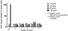 |
Fig. 18 Lactate Dehydrogenase (LDH) release of macrophage cells in contact with increasing doses of several reuse powders. Libération de lactate déshydrogénase (LDH) par des cellules macrophages en contact avec des doses croissantes de poudre réutilisée. |
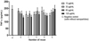 |
Fig. 19 TNF (tumor necrosis factor) production of macrophage cells in contact with increasing doses of several reuse powders. Production de TNF (facteur de nécrose tumorale) par des cellules macrophages en contact avec des doses croissantes de poudre réutilisée. |
3.2 Impact of reusing powder on the properties of printed parts
3.2.1 Density
Density does not seem to be impacted by reuse. Indeed, the results obtained by image analysis and by pycnometer are stable (Fig. 20). In the same way as for the powder granulometry, the variation of density according to the reuse is different from one study of reuse to another. Some authors see a decrease [8], others a stability [27] as in our study and some an increase [9]. This variation is due to multiple origins, indeed, it depends on the way of recycling the powder, but also on the material used.
The result shows that the stability of the powder (morphology, grain size, powder bed, moisture) allows a good fusion which results stable density. The increase of oxygen observed in the previous part does not seem to disturb the melt and consequently the density of the printed parts.
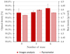 |
Fig. 20 Density and volume evolution of printed parts during reuse study. Évolution de la densité et du volume des pièces imprimées au cours de l’étude de réutilisation. |
3.2.2 Roughness
The reuse of powder does not seem to degrade the surface roughness of the parts produced in our case (Fig. 21). Our work agree with the results obtained by Del Re et al. [12] and Sukal et al. [27], whereas the studies of Ahmed et al. [8] and Seyda et al. [9] show an increase of the surface roughness with powder recycling.
The stability of the roughness could be linked to the initial roughness, which is already very high (> 30 μm). This is due to the material used, which is complex to print, and to the fact that the build plate is almost at its maximum capacity in terms of parts number.
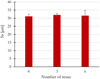 |
Fig. 21 Roughness evolution during reuse study. Évolution de la rugosité au cours de l’étude de réutilisation. |
3.2.3 Mechanical properties
Figure 22 illustrates the values of ultimate tensile strength (UTS), which remain stable along the reuses with a low standard deviation. The Rp0.2 and the elongation at break show a greater dispersion. This dispersion seems to be related to the process and not to the reuse of the powder. The reuse of the powder does not seem to impact the mechanical properties of the printed parts. This is in line with the density result.
Similar to the UTS in the tensile tests, the resilience tests are stable over reuse as shown in Figure 23. The values are relatively low, but this may be because the specimens are as-built and no stress relieving heat treatment was performed on the parts.
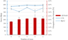 |
Fig. 22 Evolution of mechanical properties during the reuse study. Évolution des propriétés mécaniques au cours de l’étude de réutilisation. |
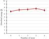 |
Fig. 23 Evolution of resilience during the reuse study. Évolution de la résilience au cours de l’étude de réutilisation. |
3.2.4 Chemical composition
The Cu/Zr, Mg/Zr and Cu/Mg ratios are plotted in Figure 24. The ratios are stable for the different reuse cycles. Nevertheless, by comparing the ratios of the chemical elements of the printed parts and those of the virgin powder, it can be noticed a significant variation from the first printing. This variation concerns the ratios Mg/Zr and Cu/Mg. The variations confirm the loss of Mg observed on the powder present in the sieving residue. It could be recommended to adjust the chemical composition of the initial powder in order to anticipate the loss of this element during the process.
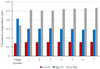 |
Fig. 24 Printed parts chemical composition evolution after reuses. Évolution de la composition chimique des pièces imprimées après réutilisation. |
4 Conclusion
The objective of this study is to observe the impact of the reuse of 6061-Zr powder during the L-PBF process on the physicochemical properties of the powder, its toxicological profile as well as the properties of the printed parts. This understanding of powder reuse on an aluminium alloy could accelerate the process of certification and standardization of the L-PBF technology for applications such as aircraft. As a reminder, the aim of this study was to reproduce an intensive and simple industrial use while isolating the impact of the reuse on the powder. For this, the printed plates were almost at their maximum capacity in terms of parts number, the reuse of the powder was carried out without addition of virgin powder and the conditioning between the cycles was simple. Indeed, only a sieving with a 63 μm mesh size was applied, in air, without drying, without mixing. The high number of parts on the build plate and the absence of virgin powder addition limited the number of reuse, which was six in this study. Nevertheless, the severe conditions used allow to know if it is possible to reuse powder according to the final application. In order to dissociate reuse from aging, the prints were made in ten days only.
Concerning the morpho-granulometry of the “free” powder (analyzed before being loaded in the machine), we noted a stability of the morphology, the granulometry as well as the specific surface along the reuse study. Moisture measurements were performed and did not show any evolution after reuse. SEM observations showed the appearance of spots on the particles. EDX analysis showed that these spots are rich in oxygen and magnesium. This could be due to the formation of aluminium and/or magnesium oxide during the process. On the other hand, this analysis can explain the increase in oxygen content between virgin and six times reused powder and the high oxygen content noticed on powder collected on the sieve. The chemical composition of the powder was compared between virgin powder, reused powder and the sieve residue. The reused particles passing through the sieve did not show any changes in chemical composition. On the other hand, the sieve residue powder showed a loss in Mg. This result confirms that sieving is an essential operation, not only to guarantee the powder granulometry but also to limit the increase of oxygen and the chemical modification of the powder.
The layered powder was also analyzed. In the same way as for the “free” powder, the particle size is not sensitive to the reuse of the powder. Nevertheless, we observed that the particle size in the layered powder is slightly smaller than the free powder introduced in the L-PBF machine. This indicates that some too large particles are not layered. As a result, the overall particle size of the alloy could be optimized to take advantage of the full particle size. This layering analysis also showed a strong stability of the powder bed density around 50%.
The toxicology study also showed a strong stability to the reuse. Indeed, the cytotoxicity and pro-inflammatory response measurements showed no variation over the reuse cycles. Thus indicates that reuse of this powder do not increase the exposition risks.
Concerning printed parts, density and mechanical properties (tensile and resilience tests) seem to be stable through the powder reuse. The chemical composition shows a loss of Magnesium between the virgin powder and the printed parts. This phenomenon, known as selective evaporation inherent to the L-PBF process, is not correlated to the reuse of powder. However, no variation of chemical composition between the printed parts through the different cycles is perceived. Similarly, no degradation of the roughness of the printed parts is noticed after the reuse of powder.
To conclude, this study shows that the oxygen content could be the limiting criterion depending on the number of reuse and the industrial applications.
Conflicts of interest
On behalf of all authors, the corresponding author states that there is no conflict of interest.
Acknowledgments
The authors wish to thank Bpifrance (Banque Publique d’Investissement), FEDER and Région Auvergne-Rhône-Alpes for the financial support of the ALMEE FUI project.
References
- W.S.W. Harun, M.S.I.N. Kamariah, N. Muhamad, et al., A review of powder additive manufacturing processes for metallic biomaterials, Powder Technol. 327, 128–151 (2018) [CrossRef] [Google Scholar]
- D. Powell, A. Rennie, D. Powell, et al., Understanding powder degradation in metal additive manufacturing to allow the upcycling of recycled powders, J. Clean. Prod. 268, 122077 (2020) [CrossRef] [Google Scholar]
- F.T. Piller, R. Poprawe, H.J. Schleifenbaum, et al., Introducing a holistic profitability model for additive manufacturing: an analysis of Laser Powder Bed Fusion, IEEE Int. Conf. Ind. Eng. Eng. Manag. 2019, 1730–1735 (2019) [Google Scholar]
- A. Smith, Opportunities for and potential contribution of social science research relating to the nature and development of Additive Manufacturing?, Proj. Cent. Bus. Relationships, Accountability, Sustain. Soc. (BRASS), Cardiff Univ., 2019 [Google Scholar]
- V. Petrovic, J. Vicente Haro Gonzalez, O. Jordá Ferrando, et al., Additive layered manufacturing: sectors of industrial application shown through case studies, Int. J. Prod. Res. 49(4), 1061–1079 (2011) [CrossRef] [Google Scholar]
- T. Fedina, J. Sundqvist, A.F.H. Kaplan, Spattering and oxidation phenomena during recycling of low alloy steel powder in Laser Powder Bed Fusion, Mater. Today Commun. 27, 102241 (2021) [CrossRef] [Google Scholar]
- S.A. Farzadfar, M.J. Murtagh, N. Venugopal, Impact of IN718 bimodal powder size distribution on the performance and productivity of Laser Powder Bed Fusion additive manufacturing process, Powder Technol. 375, 60–80 (2020) [CrossRef] [Google Scholar]
- F. Ahmed, U. Ali, D. Sarker, et al., Study of powder recycling and its effect on printed parts during Laser Powder Bed Fusion of 17-4 PH stainless steel, J. Mater. Process. Technol. 278, 116522 (2020) [CrossRef] [Google Scholar]
- V. Seyda, N. Kaufmann, C. Emmelmann, Investigation of aging processes of Ti-6Al-4V powder material in laser melting, Phys. Procedia 39, 425–431 (2012) [CrossRef] [Google Scholar]
- L. Cordova, M. Campos, T. Tinga, Revealing the effects of powder reuse for selective laser melting by powder characterization, JOM. 71(3), 1062–1072 (2019) [CrossRef] [Google Scholar]
- Y. Sun, M. Aindow, R.J. Hebert, The effect of recycling on the oxygen distribution in Ti-6Al-4V powder for additive manufacturing, Mater. High Temp. 35(1-3), 217–224 (2018) [CrossRef] [Google Scholar]
- F. Del Re, V. Contaldi, A. Astarita, et al., Statistical approach for assessing the effect of powder reuse on the final quality of AlSi10Mg parts produced by Laser Powder Bed Fusion additive manufacturing, Int. J. Adv. Manuf. Technol. 97(5-8), 2231–2240 (2018) [CrossRef] [Google Scholar]
- Officiel Prevention, La prévention des risques chimiques des métaux et composés métalliques, 2014, [Online] Available from https://www.officiel-prevention.com/dossier/protections-collectives-organisation-ergonomie/risque-chimique-2/la-prevention-des-risques-chimiques-des-metaux-et-composes-metalliques [Google Scholar]
- A.K. Lakshminarayanan, V. Balasubramanian, K. Elangovan, Effect of welding processes on tensile properties of AA6061 aluminium alloy joints, Int. J. Adv. Manuf. Technol. 40(3-4), 286–296 (2009) [CrossRef] [Google Scholar]
- C.E. Cross, On the origin of weld solidification cracking, Hot Crack. Phenom. Welds 1, 3–18 (2005) [CrossRef] [Google Scholar]
- D.L. Katgerman, D.G. Eskin, In search of the prediction of hot cracking in aluminium alloys, Hot Crack. Phenom. Welds II, 1, 3–18 (2008) [Google Scholar]
- S.Z. Uddin, L.E. Murr, C.A. Terrazas, et al., Processing and characterization of crack-free aluminum 6061 using high-temperature heating in Laser Powder Bed Fusion additive manufacturing, Addit. Manuf. 22, 405–415 (2018) [Google Scholar]
- J.H. Martin, B.D. Yahata, J.M. Hundley, et al., 3D printing of high-strength aluminium alloys, Nature 549(7672), 365–369 (2017) [CrossRef] [Google Scholar]
- A. Mehta, L. Zhou, T. Huynh, et al., Additive manufacturing and mechanical properties of the dense and crack free Zr-modified aluminum alloy 6061 fabricated by the Laser Powder Bed Fusion, Addit. Manuf. 41, 101966 (2021) [Google Scholar]
- C. Rock, C. Ledford, M. Garcia-Avila, et al., The influence of powder reuse on the properties of nickel super alloy ATI 718TM in Laser Powder Bed Fusion additive manufacturing, Metall. Mater. Trans. B Process Metall. Mater. Process. Sci. 52(2), 676–688 (2021) [CrossRef] [Google Scholar]
- R.A. Overfelt, S.I. Bakhtiyarov, R.E. Taylor, Thermophysical properties of A201, A319, and A356 aluminium casting alloys, High Temp. – High Press. 34(4), 401–409 (2002) [CrossRef] [Google Scholar]
- Z.Y. Deng, J.M.F. Ferreira, Y. Tanaka, et al., Physicochemical mechanism for the continuous reaction of γ-Al2O3-modified aluminum powder with water, J. Am. Ceram. Soc. 90(5), 1521–1526 (2007) [CrossRef] [Google Scholar]
- M. Karimpour, S.R. Eatezadi, S. Hasani, et al., The oxidation mechanism of pure magnesium powder particles: a mathematical approach, Metall. Mater. Trans. B Process Metall. Mater. Process. Sci. 50(4), 1597–1607 (2019) [CrossRef] [Google Scholar]
- M.P. Mallamaci, S. Ramamurthy, C. Barry Carter, Liquid infiltration of MgO and Al2O3 thin films, MRS Proc. 318, 9668–9672 (1993) [CrossRef] [Google Scholar]
- K. Riener, S. Oswald, M. Winkler, et al., Influence of storage conditions and reconditioning of AlSi10Mg powder on the quality of parts produced by Laser Powder Bed Fusion (LPBF), Addit. Manuf. 39, 101896 (2021) [Google Scholar]
- W. Stopyra, K. Gruber, I. Smolina, et al., Laser Powder Bed Fusion of AA7075 alloy: influence of process parameters on porosity and hot cracking, Addit. Manuf. 35, 101270 (2020) [Google Scholar]
- J.A.N. Sukal, D. Palousek, D. Koutny, The effect of recycling powder steel on porosity and surface roughness of SLM parts, MM Sci. J. 2018, 2643–2647 (2018) [CrossRef] [Google Scholar]
Cite this article as: Maxime Beal, Mohamed-Nour Azzougagh, Jérémie Pourchez, Philippe Bertrand, Elodie Cabrol, Hocine Si-Mohand, Francois-Xavier Keller, Effect of powder reuse on physical, chemical and toxicological properties of 6061-Zr aluminum alloy processed by Laser Powder Bed Fusion (L-PBF), Matériaux & Techniques 111, 103 (2023)
All Figures
|
Fig. 1 Schematic illustration of gourds concept to analyze the powder layered during L-PBF process: (a) the roller spread the new layer; (b) the layer is spread and ready to be melted; (c) the laser solidify the contour (the gourd) to imprison the layered powder; (d) the gourd is ready for the next layer; (e) finished gourd ready to be analyzed. Illustration schématique du concept de gourde pour analyser la couche de poudre pendant le processus L-PBF : (a) le rouleau étale la nouvelle couche ; (b) la couche est étalée et prête à être fondue ; (c) le laser solidifie le contour (de la gourde) pour emprisonner la couche de poudre ; (d) la gourde est prête pour la couche suivante ; (e) la gourde finie prête à être analysée. |
| In the text | |
|
Fig. 2 Schematic illustration of pollution mechanism during L-PBF. Illustration schématique du mécanisme de pollution pendant le procédé L-PBF. |
| In the text | |
|
Fig. 3 Print sequence during reuse study: (a) powder loading; (b) characterization plate print; (c) fins print to use the powder still in the feeding piston; (d) sieving process to recycle the powder in order to reuse it for the next print. Séquences d’impression pendant l’étude de réutilisation : (a) chargement de la poudre ; (b) impression du plateau de caractérisation ; (c) impression des ailettes pour utiliser la poudre encore présente dans le piston d’alimentation ; (d) processus de tamisage pour recycler la poudre afin de la réutiliser pour l’impression suivante. |
| In the text | |
|
Fig. 4 Fins prints after (a) 0 reuse, (b) 1 reuse and (c) 2 reuse of powder. Impressions des ailettes après (a) 0 réutilisation, (b) 1 réutilisation et (c) 2 réutilisations de la poudre. |
| In the text | |
|
Fig. 5 Diagram of powder reuse steps. Diagramme des étapes de réutilisation de la poudre. |
| In the text | |
|
Fig. 6 Equivalent diameter for each reuse cycle. Diamètre équivalent pour chaque cycle de réutilisation. |
| In the text | |
|
Fig. 7 SEM images from virgin powder, 6x used powder and residual powder from sieving: (a) small round virgin particle; (b) big round virgin particle; (c) porous particle; (d) aggregates; (e) deformed particle; (f) coarse aggregate particle (Deq < 63 μm); (g) coarse aggregate with satellites (Deq > 63 μm); (h) big round particle thermally affected (Deq > 63 μm). Images MEB de la poudre vierge, de la poudre utilisée 6x et de la poudre résiduelle après le tamisage : (a) petite particule ronde vierge ; (b) grosse particule ronde vierge ; (c) particule poreuse ; (d) agrégats ; (e) particule déformée ; (f) particule agrégée grossière (Deq < 63 µm) ; (g) agrégat grossier avec satellites (Deq > 63 µm) ; (h) grosse particule ronde affectée thermiquement (Deq > 63 µm). |
| In the text | |
|
Fig. 8 Roundness and equivalent diameter of virgin powder, 6 times reused powder and sieving residue. Circularité et diamètre équivalent de la poudre vierge, de la poudre réutilisée 6 fois et du résidu de tamisage. |
| In the text | |
|
Fig. 9 Specific surface area for each reuse cycle. Surface spécifique pour chaque cycle de réutilisation. |
| In the text | |
|
Fig. 10 Particle size of powder bed for each reuse cycle. Taille des particules du lit de poudre pour chaque cycle de réutilisation. |
| In the text | |
|
Fig. 11 SEM pictures of thermally affected powder in powder bed after first use. Images SEM de la poudre affectée thermiquement dans le lit de poudre après la première utilisation. |
| In the text | |
|
Fig. 12 Powder bed density for each reuse cycle. Densité du lit de poudre pour chaque cycle de réutilisation. |
| In the text | |
|
Fig. 13 Oxygen content of virgin powder, 6 times reused powder and sieving residue. Teneur en oxygène de la poudre vierge, de la poudre réutilisée 6 fois et du résidu de tamisage. |
| In the text | |
|
Fig. 14 (a) SEM pictures of thermally affected powder and (b) EDS analysis of oxygen. (a) Images MEB de la poudre affectée thermiquement et (b) analyse par EDS de l’oxygène. |
| In the text | |
|
Fig. 15 SEM pictures of thermally affected powder and EDS analysis. Images MEB de la poudre affectée thermiquement et analyses EDS. |
| In the text | |
|
Fig. 16 Mass loss of virgin powder and reused powder. Perte de masse de la poudre vierge et de la poudre réutilisée. |
| In the text | |
|
Fig. 17 Evolution of the elemental chemical composition of the powder. Évolution de la composition chimique de la poudre. |
| In the text | |
|
Fig. 18 Lactate Dehydrogenase (LDH) release of macrophage cells in contact with increasing doses of several reuse powders. Libération de lactate déshydrogénase (LDH) par des cellules macrophages en contact avec des doses croissantes de poudre réutilisée. |
| In the text | |
|
Fig. 19 TNF (tumor necrosis factor) production of macrophage cells in contact with increasing doses of several reuse powders. Production de TNF (facteur de nécrose tumorale) par des cellules macrophages en contact avec des doses croissantes de poudre réutilisée. |
| In the text | |
|
Fig. 20 Density and volume evolution of printed parts during reuse study. Évolution de la densité et du volume des pièces imprimées au cours de l’étude de réutilisation. |
| In the text | |
|
Fig. 21 Roughness evolution during reuse study. Évolution de la rugosité au cours de l’étude de réutilisation. |
| In the text | |
|
Fig. 22 Evolution of mechanical properties during the reuse study. Évolution des propriétés mécaniques au cours de l’étude de réutilisation. |
| In the text | |
|
Fig. 23 Evolution of resilience during the reuse study. Évolution de la résilience au cours de l’étude de réutilisation. |
| In the text | |
|
Fig. 24 Printed parts chemical composition evolution after reuses. Évolution de la composition chimique des pièces imprimées après réutilisation. |
| In the text | |
Current usage metrics show cumulative count of Article Views (full-text article views including HTML views, PDF and ePub downloads, according to the available data) and Abstracts Views on Vision4Press platform.
Data correspond to usage on the plateform after 2015. The current usage metrics is available 48-96 hours after online publication and is updated daily on week days.
Initial download of the metrics may take a while.