")
")
| Issue |
Matériaux & Techniques
Volume 106, Number 4, 2018
|
|
|---|---|---|
| Article Number | 401 | |
| Number of page(s) | 10 | |
| Section | Matériaux inorganiques / Inorganic materials | |
| DOI | https://doi.org/10.1051/mattech/2018041 | |
| Published online | 05 December 2018 | |
Regular Article
Study of the performance of adobe brick coated for sustainable construction in the Algerian Sahara
Étude des performances de briques d’adobe enduites pour une construction durable au Sahara algérien
1
EPAU-Polytechnic school of architecture and urbanism,
Algiers, Algeria
2
Laboratory of City, Environment, Society and Sustainable Development, University of Med Boudiaf,
M’sila, Algeria
* e-mail: This email address is being protected from spambots. You need JavaScript enabled to view it.
Received:
9
March
2018
Accepted:
13
August
2018
Abstract
This article describes a study conducted to determine the ideal both traditional and stabilized composition of adobe as a building material, and to further refine an appropriate choice of coating composition for extended durability of these constructions in adobe: choose the suitable coating that fits the most with its substrate. The constructions in Z’gueg El Hadjadj [Laghouat town, Algeria] consist of adobe walls but also plaster that serves as a coating for these brick walls. The degradation phenomena of the building are considered in the adobe-coated couple, and consequently in the suitability of their compositions. The compatibility of plasters with adobes remains a major factor in the restoration and conservation of earthen constructions. This paper examines the results of the experimental characterization of the behavior of coated bricks, which consists of studying in the laboratory the water resistance: the drying-wetting test and the capillary rise test, as well as the complementary accelerated aging test: the abrasion test. These tests will be supplemented by another test, that of the adhesion, to see the compatibility of the coatings with their supports. The results, compared below, led to the conclusion that for capillary absorption and adhesion tests, a homogeneous coating in 3 layers could give more conclusive results. The drying-wetting test is recommended especially for bulk and surface treated samples.
Résumé
Le présent article décrit une étude menée pour déterminer la composition idéale à la fois traditionnelle et stabilisée de l’adobe comme matériau de construction, et de peaufiner encore davantage un choix approprié de la composition d’enduit pour une durabilité prolongée de ces constructions in adobe : choisir le revêtement adapté qui s’ajuste le plus avec son substrat. Les constructions à Z’gueg El Hadjadj (ville de Laghouat, Algérie) sont constituées de murs d’adobes mais aussi d’enduit qui sert de revêtement pour ces murs en briques. Les phénomènes de dégradation de la bâtisse se considèrent dans le couple adobe-enduit, et par conséquent dans la convenance de leurs compositions. La compatibilité des enduits avec les adobes demeure un facteur principal dans la restauration et la conservation des constructions en terre. Le présent document examine les résultats de la caractérisation expérimentale du comportement des briques enduites qui consiste à étudier au laboratoire la tenue à l’eau : le test de séchage-mouillage et le test de remontée capillaire, ainsi que l’essai de vieillissement accéléré complémentaire : l’essai d’abrasion. Ces tests seront complétés par un autre essai, celui de l’adhérence, pour voir la compatibilité des enduits avec leurs supports. Les résultats, comparés ci-dessous, ont conduit à la conclusion que pour les essais d’absorption capillaire et d’adhérence, un enduit homogène en 3 couches pourrait donner des résultats plus concluants. L’essai de séchage-mouillage est recommandé surtout pour des échantillons traités en masse et en surface.
Key words: adobe brick / coatings / absorption / adhesion / durability
Mots clés : brique d’adobe / enduits / absorption / adhérence / durabilité
© N. Kerroum et al., published by EDP Sciences, 2018
 This is an Open Access article distributed under the terms of the Creative Commons Attribution License (http://creativecommons.org/licenses/by/4.0), which permits unrestricted use, distribution, and reproduction in any medium, provided the original work is properly cited.
1 Introduction
Most searches engaged in the study of the use of local earth-based building materials [1] have focused on the reinforcement of the adobe as a material (traditional adobe), or moreover on the stabilized adobe where a good stabilizer [2] is added to the purpose of improving the physical and mechanical characteristics of the material [3,4].
The construction of Z’gueg El Hadhadj1 district has obeyed many architectural rules. The stone foundations repose walls of adobe bricks “attub”: A mixture of earth and straw according to a procedure that consist in moulding the raw material in wooden moulds and then drying them in the sun, these adobe walls insulate from the heat and the cold. The neighborhood built from adobe, as a main material, takes its color from its homeland, that is going from ochre to brown (Fig. 1).
The preservation of historic land architectures [1] is a committed approach in many countries that seeks a restoration and enhancement of heritage buildings, whose cultural importance is a major importance for people. Beyond an intervention in a few isolated buildings, nowadays there is preservation of larger sites [5].
The preservation of earthen constructions poses delicate problems, because the earthen material needs appropriate treatments which can exclude the techniques of restoration adapted to other materials: problem of waterproof coatings for instance, which may activate a wet pathology “dam of the evaporation with the water vapour migrating through walls” problems of know-how allowing a restoration of buildings with the original constructions techniques [5].
The raw earthen buildings are perpetually exposed to climatic fluctuations. The solicitations sometimes are extremes from climatic alternations that have caused important degradations of the earthen material [6]. The mechanisms involved in decay are the same as the actions that cause weathering. The expansion and contraction resulting from changes in temperature and humidity may induce cracking and concomitant deterioration [7]. The survival of constructions is endangered. The degradations of the observed materials cause often an erosion of the construction which may go till its partial and even its total collapse.
Z’gueg El Hadjadj is a district whose earthen houses represent a precious cultural heritage to Laghouat city (Fig. 2). This architectural and historical heritage hasn’t been neither the object of serious global inventory campaign nor centralized protection. Many houses stayed unoccupied and are intended ruin .The first consequence of the abandonment and the ruin of this rich heritage is depreciation of the earthen material: we attribute its poor properties and weak durability. Thereby, the population abandons it and only the deprived people deign to use it. To withstand these hostile prejudices for the worry of rehabilitation of the earthen constructions, an information campaign and an investigation are needed [8]. The collection of evidences and writings about both the ancient and new heritage and the observations settled allow surrounding the real problems, related to the behavior in times and to the use of this kind of constructions [9].
In 2000, at Lagouhat University, a study of durability of the straw coated adobe was made by F. Aouissi, being the subject of experimental investigation on many composition of coatings, using to protect the surface of adobe wall [10]. The coated samples have been submitted to the shower test to prove the water resistance of the bricks. Ten years; later these about the samples has been stored in the laboratory of civil engineering at Laghouat University.
The objective of this experimentation is to continue in the same thinking of the investigation: the study of the sustainability of these coatings [8,9], choosing particularly other complementary tests. The same samples will be then submitted this time to the test of abrasion [11], called also the test of the wire brush (introduced by CRATerre but still not published) and to the Pull of test to see the adhesion behavior of these coatings toward the adobe [12,13]. Continuing in the same axis of the research is to draw near to take a decision about the coating to be adopted for night choosing the appropriated one and to recommend it for all the participants in the restoration process.
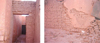 |
Fig. 1 A typical example of decrepit of an adobe wall. Source: 3rd year students of architecture department (2005–2006). Exemple typique de décrépitude d’un mur en adobe. Source : Étudiants département architecture 3e année (2005–2006). |
 |
Fig. 2 Architectural qualities of the district. Source: 3rd year students of architecture department (2005–2006). Qualités architecturales du quartier. Source : Étudiants département architecture 3e année (2005–2006). |
2 Coatings used in the tests
The coating applied on the brick samples has been done in three layers, the first layer ranging from 2 to 4 mm thick, composed of high doses of sand and binder, applied directly on the surface, the second layer from 8 to 20 mm realised by mixing the sand and the binder which are smaller in size than those used in the first layer. The third one or the decorative layer is composed mainly of thin sand and relatively a weak dosage of binder, its thickness ranging from 5 to 8 mm. Two types of coatings were chosen in this study:
-
traditional coating without earth;
-
traditional coating with earth.
The composition of each variant coating tested is made from the following components (Tab. 1).
We designate by [10].
-
BS: big sand
-
FS: fine sand
-
C: cement
-
MS: medium sand
-
L: lime
-
E: earth
3 Material and methods
The specimen of tests
The bricks intended to be tested, stored in a sheltered spot in one of the rooms of the laboratory that are older than 10 years, will be examined in normal conditions of the laboratory at a temperature of 23 ± 2 °C.
A high precision scale will be used in the weighting of samples in accordance with the weighing requirements.
3.1 Drying-wetting test
It is a test of accelerated aging, which allows obtaining the information about the durability of the material through times.
The objective is to know in a short time, the behavior of the bloc submitted to repeated cycles including harsh conservation conditions. The presented process is the one of ASTM 559 standard and of AASHO T135 [5]. The specimens are completely immersed in water, at the temperature of the work place, during 5 h. After the test, pieces are removed from the water and then dried in a drying oven of 71 °C for 42 h, then they are removed from the oven and brushed one by one. This brushing is carried out using a wire brush and helps to remove all fragments of material affected by the wetting and drying cycles. The brushing is firm and concerns each place of the specimens in both directions (up and down), totaling 18 to 25 brush strokes [5]. The applied force in the brushing is of 1.5 kg. The above-described process constitutes in a cycle of 42 h of drying-wetting. The test pieces are then immersed in water again, and subjected to another drying-wetting cycle. The process is repeated twelve times. For reasons of restriction of the number of samples available in the place, only 3 types of traditional coatings, each in 3 layers, will be tested, particularly samples C1, C9 and C10.
3.2 Capillarity test
To draw near the real conditions of using earth material, we preferred to execute the test of capillarity, which is representative of the action of water during the rise of capillarity in the walls (accumulation of rain water in the bottom of the wall). This part is devoted to the observation of coated bricks behavior in front of a rise of capillarity test. To be done, these samples will undergo partial immersions in a container full of water. Weightings will be made at varying time intervals depending on the speed of water absorption.
The test of water absorption aims to determine the quantity of water absorbed by the capillarity. This test consists to weight the increase about the mass of the samples placed in the water container in which the water level is maintained at 5 mm above the inferior face of the samples. It allows as well determining the speed of water absorption of the earthen blocs in function of time and we deduce the time at which the specimen is saturated with water.
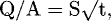
The pre-dried samples are placed vertically in a plastic container containing water above small carriers according the schema indicated in Figure 3, so that the water does not touch the specimen that is higher than 5 mm of the bowl depth, the rest of the sample is previously waterproofed by a water proof tape on all the other surfaces. Then, we measure the increase of the mass of the sample in function of time at 5, 10, 20, 40, 60, 90, 120, 180 and 240 min.
For this test, five types of traditional coatings “sand, lime, cement” will be tested, including two earth-based. These coatings in 3 layers were applied on straw adobes of 29 × 14 × 9 cm3. The sample will be placed vertically in waterproof container on the two supports designed for this purpose. To avoid the water infiltration in the lateral sides of the sample, a water proof tape will be provided on the entire circumference of the brick. The measurements were performed with an electronic balance (Fig. 4). Before each weighting, the basic of the sample will be wiped by a damp cloth. These operations are performed as soon as possible and continued until saturation of the brick. Before starting the test, the samples will be pre-conditioned by drying them in a drying oven at about 105 °C, until constant mass. They will be then measured, and then put in contact with water at 5 mm depth. The small surface of the sample (the immersed face) will be measured and recorded. The weight gain will be as well measured at many moments during 13 h and 20 min (typically 5, 10, 20, 40, 60, 90, 120, 180 and 240 min). The absorption test results of the different bricks, will be presented by drawing all the straight lines left on the segments of the increase masses of the samples according to the square root of time. As the equation:
 (1)
where:
(1)
where:
-
Q: the quantity of water absorbed in [cm3];
-
A: the surface of the specimen in contact with water [cm2];
-
t: time [s];
-
S: the absorption coefficient of the specimen [cm/s1/2].
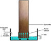 |
Fig. 3 Diagram of absorption test device. Diagramme du dispositif d’essai d’absorption. |
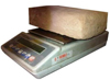 |
Fig. 4 Balance of accuracy 0.1 g. Balance de précision 0.1 g. |
3.3 Test of resistance to abrasion
Based on the test: ASTM-D4977, standard Test Method for Granule Adhesion, to Mineral Surfaced Roofing by Abrasion. A wire brush, horizontally immobilized and vertically charged with a weight of 6 kg, is used to scrub the surface of the sample following the rectilinear movement “back and forth” of the sample over a 150 mm stroke. The weight of the quantity of detached grains is estimated by measuring the result of this abrasion test.
Nine types of traditional coatings will be tested, “sand, lime and cement”, including two earth-based. These coatings in 3 layers, except for the composition number 8 which is monolayer, were applied to straw adobe of 29 × 14 × 9 cm3.
Tests on the straw adobe without coating (clay substrate without coating) will be realized to detect the difference of resistance to abrasion when stabilized coatings are applied to them. The substrate samples bricks provided for this trial has 290 × 140 × 90 mm3 dimensions, but samples with optionally their coatings have more or less variable dimensions depending on the application of the coating, knowing that the later fully surrounds the substrate. The direction of the length is the same as that of the device. The surface of 150 × 115 mm2 rubbed by the brush will be performed on the surface of 290 × 140 mm2 of the adobe (Fig. 5). The weight in grams of grains that are detached in the abrasion test shall be calculated as follows:
 (2)
where:
(2)
where:
-
P: weight of the detached grains;
-
A: weight of the sample before the test [g];
-
B: weight of the sample after the test [g].
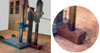 |
Fig. 5 Coring device. Dispositif de carottage. |
3.4 Pull-off test
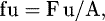
Called also the adhesion quantifying test or the split between two materials. This test is used to provide information about the pull off properties of the different coatings on their substrate. It can be performed by traction, by bending and/or by direct or indirect shear [14]. Based on the standard EN1015-12 (methods of test for mortar for masonry). The adhesion force is measured as the maximum constraint of the traction by direct perpendicular load on the mortar surface of coating applied on a support. The traction force is applied on traction pastille defined, stuck on the surface to the test of mortar. The adhesion force is the link of the split load and the correspondent surface. The test consists on measuring using a pull tester with which a pellet is pulled (50 mm) of the coating surface previously cut with a core drill to a depth a little greater than that of the coating. A metal disc, in pellet form, completed by a threaded rod will be glued later on the coating in order to exercise a traction force, in order to apply a traction effort using a tearing device and to measure the extraction force [14]. This test and its results processing are very quick to be performed. We deduce the pull force and we define the split mode for each test. The split may be cohesive in the support or the mortar; it can also be adhesive, that is to say it depends on the interface; or mixed, both cohesive and adhesive. For this type of test, in order to a tested product will be considered conform to the requirements, a larger proportion of cohesive failure in the support is required [14].
The core drill tube must penetrate the sample across the entire surface and penetrate into the substrate within about 5 mm depth (Fig. 5). On the surface, a metal pastille having the same diameter is stuck with a fast adhesive of the brand ALTECO 3-TON QUICK EPOXY, available on the market. The adhesion test consists of applying on the ball head a normal traction effort on the pastille surface.
Thereby, we obtain the value of adhesion (daN) of the coating on its support, if the split occurs according the plan of contact. The same samples used in the previous abrasion test, will be used this time in the core drill, but the use will be on the second face of the samples, the one which had not been brushed.
Then, these samples will undergo the tests according to the specifications previously noted in the general specifications of adhesion test in Figure 6.
The drawback in this type of test is the fact that we do not necessarily characterize the interface, since the split may be cohesive in the support, or in the mortar. The main consequence is then the wide dispersion of results and the large number of tests to be performed [14]. The adhesion force was calculated at 0.05 N.mm−2
near:
 where:
-
fu: adhesion force [N/mm2];
-
F u: the split load [N];
-
A: the test surface of the cylindrical sample [mm2].
 |
Fig. 6 Setting up sample in the test device. Mise en place de l’échantillon dans le dispositif d’essai. |
4 Results and discussion
4.1 Drying-wetting test
After immersion of the 3 samples (C1, C9 and C10) for a duration of 5 h in water. After the allotted time, the samples are disintegrated in water, where big cracks were observed on each specimen. The coatings stabilized with cement and/or lime are not directly damaged after their contact of 5 h with water, but it was rather the substrate adobe-earth straw untreated which finally gives up and becomes completely wet, and it was decomposed in the tray. In conclusion, this test proved to be extremely severe. It does not seem to be suitable for predicting the water resistance of these types of samples.
4.2 Capillarity test
The Table 2 gives the quantity of water absorbed by the samples in function of time.
Figure 7 presents the evolution of the rate of absorption according to the coating dosage in cement and lime for various period of immersion. It is observed for the C7, where the 3 layers containing cement, that the quantity of water absorption by capillarity remains the lowest. This phenomenon may be explained by the fact that cement helps to reduce the porosity of the coating. Compared with all samples, the C3 absorbs a large amount of water. This phenomenon is opposite to that observed with the cement dosage. It can be explained by the fact that, according to P. Maurenbrecher et al., the mortar with a high lime content (2 to 3 times more lime than cement by volume) is more porous than a cement mortar.
The overall porosity of the coating being higher, the tendency to absorb water is then greater. For C4, C5 and C6, their tendencies are closed to the C7.
We note for the samples of C4 and C5, the tendency of an ability of capillary absorption are almost identical with a saturation time respectively equal to 400 and 600 for 2 min knowing that for two volumes of cement, the 3rd layer of C4 contains 3 times lime volume than that of C5; this similarity is due to the different dosage of the other layers (the 1st and the 2nd)
Quantity of water absorbed by the specimens in function of time.
Quantités d’eau absorbées par les échantillons en fonction du temps.
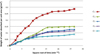 |
Fig. 7 Variation in the quantity of water absorbed per unit area in over time. Variation de la quantité d’eau absorbée par unité de surface dans le temps. |
4.3 Test of the abrasion resistance
This abrasion resistance test was used to assess the degree of cohesion force imparted to the coatings through different formulations. The coefficient of abrasion resistance is measured in g.cm−2, the weight of the detached grains when the coating is subjected to a series of brush 50 cycles “to and” under a weight of 6 kg; this released amount will be reported to the brushed surface. During the course of the tests no complication was found as to the adhesion of the coatings to their substrates (no visible detachment). The only test performed on one piece of coating without its substrate is the one brought from the site Z’gueg El Hadjadj, and it was not a constraint since the test that was performed exclusively on the surface of the coating, regardless of the shape and size of the test sample. The only encountered problems are those with its adjustment, its adaptation and its immobilization l in the test device. The test results are displayed in Table 3.
The coating of C4 whose last layer is composed of 2 FS + 1.5 L + 1C displays the best resistance to this abrasion test with 0.002 g/cm2, followed by the earth based coatings of C9 and C10 whose 3rd layers are composed of 1 FS + 1/4C and 1 FS + 1 L + 1/2C with 0.003 g/cm2 each. Comparing to the coatings previously mentioned, the coatings of C3 whose 3rd layer is composed of 2 FS + L + 1/8C and C2 whose the last layer is composed of 2FS + 1L show a very weak resistance with respectively 0.035 and 0.043 g.cm−2, for the coating brought from the site, the latter produces the lowest resistance with 0.051 g.cm−2 (Figs. 8 and 9).
Evaluation
A: Excellent ≤ 0.003 g.cm−2;
B: Good 0.004 g/cm2 to 0.028 g.cm−2;
C: Acceptable 0.028 g/cm2 to 0.051 g.cm−2;
D: Poor > 0.051 g.cm−2.
And it is constantly C4, which with the addition of cement in the composition of the coating layers was necessary to ensure good adhesion of the latter to the earth support and which enters into the appropriate binders assays recommended by F. Aouissi [10] (Tab. 4).
Compared to its substrate, the sample of coating brought from the site displays an abrasion resistance of 13.6 times higher, because the tested adobe does not present any obvious chemical stabilization, except for a few strands of straw and some impurities, unlike its coating which is by different composition of whitish color with the presence of whitewash layer on the decorative layer.
In conclusion, the coefficient of abrasion of all coatings, in which the third layer is made from cement and thin sand, have recorded better results, contrary to those of C2 and C3, which showed different coefficients. This is probably due to the existence of the small amount of cement (C3) or, to its total absence from the composition (C2). Also, as we have seen, the presence of lime in increase quantity in the compositions affects continuously the growth of this coefficient. For the coating, the use of lime, mixed with very little cement (1/10) allows to make the coating more resistant and thus capable of withstanding the climate change, neither blocking the steam circulation through walls, nor being too rigid and thus maintaining the homogeneity of the transverse rheological characteristics of the wall [15].
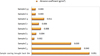 |
Fig. 8 Abrasion resistance of the various coatings. Résistance à l’abrasion des différents enduits. |
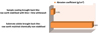 |
Fig. 9 Comparison of the abrasion resistance of the coating on its support. Comparaison de la résistance à l’abrasion de l’enduit et de son support. |
Dosing of binders used in the appropriated coating.
Dosage des liants utilisés dans le revêtement approprié.
4.5 Pull-off test
During the execution of coring, and before the rotary drill bit reaches the adobe support, splits were made according to plans situated in the coating. The coring is shown as extremely severe for this type of material and this despite the use of different speeds of the core drill (from a faster speed to a slower speed). Of the nine coatings planned for the adhesion test, two only have hardly passed the examination of core, C2 and C9 and another one which was not initially foreseen to be tested. It is the sample C11, the coating is applied to the support earth straw is an industrial one.
According to F. Aouissi [10], it is a finished product of gray color based on cement, fine sand and resin powder, to which water is added until obtaining a very sticky plastic tab that has been applied to the four faces of the brick. During its application, F. Aouissi has found out that regardless of the land type, the coating in question, in which the drying lasted only for 48 h without any appearance of cracks, present an excellent adhesion on the sides of the bricks. Contrary to the compositions used in the manufacture of coatings without earth and based on lime, this really doesn’t seem to have succeeded to overcome the adhesion problem on the support, according to the cracks observed in some bricks after the application of the third coating layer [10].
During the pull of test for the two samples C2 and C9, the stuck pastilles have tendency to tear of the bricks very fast (splits according plans situated in the coating). This doesn’t allow us to draw any conclusion, except that the pull tester is designed more for the cement concrete than for the earthen material.
For the C11, and following the traction effort applied on the pastille, the split is done according a plan gives us an adhesion force of fu = 0.102 N.mm−2.
In conclusion, this test has proved to be not predicative. The device of the test doesn’t seem to be adapted for the earthen material.
5 Conclusion
In the four tests performed, there is test method of abrasion that had been persuasive, controlled and reproducible. It is also important to note that the classification of materials, according to their performances in this test, informs us about their durability based on reality. And may serve to provide rapidly predictive information about the surface and the quality of stabilized cement and/or lime coatings or other similar materials. The sustainability of the constructions on earth remains a permanent concern regardless to the place where they are built. Thus, there is a need for a test approach, which is simple and cheap. The complexity of the samples taken for this test program depends on the diversity of the coating components and the diversity of the 3 layers applied on the support. For the capillary, absorption, and adhesion tests, a homogenous coating of three layers may give results that are more conclusive. The drying-wetting test is recommended especially for the treated samples in mass and surface.
Finally, our future study is based on the preparation of a coating reinforced by vegetal fibers chemically treated and short length in order to have a better interfacial compatibility.
References
- P.I. Valverde, R. Fuentes, E.I. Valverde, M.M. Martín, Á.C. Del Moral, M.L. Delgado, J. Santos, P.E. Canals Projected earth system. Aplicación de esta técnica a la construcción de viviendas sostenibles y ecológicas: ECODOME. XI Congreso Internacional de Rehabilitación del Patrimonio Arquitectónico y Edificación, 2012, pp. 556–564 [Google Scholar]
- G. Ruiz, L. Delgado, E. Hernandez, Edificaciones de bajo coste. Editado por ONG SUR, Madrid, Espana, 1993 [Google Scholar]
- V.F. Perez de Salazar, Tecnologia de la Arquitectura con tierra sin cocimiento. Tesis, Facultad de Arquitectura. Division de Estudios de Postgrado, Mexico D. F. Mexico, 1989 [Google Scholar]
- U. Tejada Schmidt, Tecnicas de preparacion y estabilizacion del adobe. V Curso Internacional sobre edificaciones de bajo costo en zonas sismicas. Octubre (1993). Editado por CISMID (Centro peruano japones de investigacion sismica y mitigacion de desastres [Google Scholar]
- C.M.F. Vieira, T.M. Soares, R. Sanchez, S.N. Monteiro, Incorporation of granite waste in red ceramics, Mater. Sci. Eng. A, 373, 115 (2004) [CrossRef] [Google Scholar]
- E.A. Dominguez, R. Ullmann, Ecological bricks’ made with clays and steel dust pollutants, Appl. Clay Sci. 11, 237 (1996) [CrossRef] [Google Scholar]
- H.H.M. Darweesh, Building materials from siliceous clay and low grade dolomite rocks, Ceram. Int. 27, 45 (2000) [CrossRef] [Google Scholar]
- H.S. Ferreira, G.A. Neves, H.C. Ferreira, M.C. Silva, Reciclagem de Residuos Industriais Provenientes de Serragem de Granitos para uso na Composicao de Massa para Confeccao de Revestimentos Ceramicos, in Proc 45th Brazilian Congress of Ceramic, Florianopolis-SC, Brazil, 2001, pp. 1–12 [Google Scholar]
- G.A. Neves, Reciclagem de Residuos da Serragem de Granitos para Uso como Materia-Prima Ceramica, Ph.D. Thesis, Federal University of Campina Grande, Campina Grande, Paraiba, Brazil, 2002 [Google Scholar]
- G.C. Xavier, F. Saboya, P.C. Maia, J. Alexandre, Durability of fired clay bricks containing granite powder. Mater. Constr. 62, 213 (2012) [CrossRef] [Google Scholar]
- K. Zoghlami, Intrinsic factors determining the physical behaviour and durability of the Miocene sandstones used to built the Zeghouan-Carthage aqueduct (Tunis). Mater. Constr. 54(276), 35–49 (2004) [Google Scholar]
- M.A. Rodriguez, B. Saroza, Determination of the optimum composition of adobe brick for a school in Cuba, Mater. Constr. 56(282), 53–54 (2006), Spain. [Google Scholar]
- G. Barrios, L. Alvarez, H. Arcos, E. Marchant, D. Rosi, La Tierra, material de Construccion, Inf. Constr., Instituto Eduardo Torroja 37(377), 43 (1987) [Google Scholar]
- H. Houben, H. Guillaud, Traité de construction en terre, CRATerre éditions Parenthèses, Marseille, 2006 [Google Scholar]
- O. Myriam, Le materiau terre, compactage, comportement, application aux structures en blocs de terre, Thèse de doctorat, I.N.S.A-Lyon, 1994 [Google Scholar]
District in Laghouat city, which by its position, represents the gateway to the Saharan areas, situated in the bottom of the foothills of djebel Amour (mountain Amour), 432 km south of Algiers on the axis of the national road no 1 linking the capital to the south of the country, about 751 height, 33°41’ of latitude north and 2°53’ longitude east.
Cite this article as: Nadir Kerroum, Brahim Nouibat, Azzedine Benyahia, Ali Redjem, Study of the performance of adobe brick coated for sustainable construction in the Algerian Sahara, Matériaux & Techniques 106, 401 (2018)
All Tables
Quantity of water absorbed by the specimens in function of time.
Quantités d’eau absorbées par les échantillons en fonction du temps.
Dosing of binders used in the appropriated coating.
Dosage des liants utilisés dans le revêtement approprié.
All Figures
|
Fig. 1 A typical example of decrepit of an adobe wall. Source: 3rd year students of architecture department (2005–2006). Exemple typique de décrépitude d’un mur en adobe. Source : Étudiants département architecture 3e année (2005–2006). |
| In the text | |
|
Fig. 2 Architectural qualities of the district. Source: 3rd year students of architecture department (2005–2006). Qualités architecturales du quartier. Source : Étudiants département architecture 3e année (2005–2006). |
| In the text | |
|
Fig. 3 Diagram of absorption test device. Diagramme du dispositif d’essai d’absorption. |
| In the text | |
|
Fig. 4 Balance of accuracy 0.1 g. Balance de précision 0.1 g. |
| In the text | |
|
Fig. 5 Coring device. Dispositif de carottage. |
| In the text | |
|
Fig. 6 Setting up sample in the test device. Mise en place de l’échantillon dans le dispositif d’essai. |
| In the text | |
|
Fig. 7 Variation in the quantity of water absorbed per unit area in over time. Variation de la quantité d’eau absorbée par unité de surface dans le temps. |
| In the text | |
|
Fig. 8 Abrasion resistance of the various coatings. Résistance à l’abrasion des différents enduits. |
| In the text | |
|
Fig. 9 Comparison of the abrasion resistance of the coating on its support. Comparaison de la résistance à l’abrasion de l’enduit et de son support. |
| In the text | |
Current usage metrics show cumulative count of Article Views (full-text article views including HTML views, PDF and ePub downloads, according to the available data) and Abstracts Views on Vision4Press platform.
Data correspond to usage on the plateform after 2015. The current usage metrics is available 48-96 hours after online publication and is updated daily on week days.
Initial download of the metrics may take a while.