")
")
| Issue |
Matériaux & Techniques
Volume 109, Number 3-4, 2021
Special Issue on ‘Overview, state of the art, recent developments and future trends regarding Hydrogen route for a green steel making process’, edited by Ismael Matino and Valentina Colla
|
|
|---|---|---|
| Article Number | 303 | |
| Number of page(s) | 10 | |
| Section | Métaux et alliages / Metals and alloys | |
| DOI | https://doi.org/10.1051/mattech/2021025 | |
| Published online | 03 February 2022 | |
Regular Article
Hydrogen steelmaking. Part 1: Physical chemistry and process metallurgy☆
1
Université de Lorraine, IJL, Labex DAMAS,
Nancy, France
2
IF Steelman,
Metz, France
* e-mail: This email address is being protected from spambots. You need JavaScript enabled to view it.
Received:
27
October
2021
Accepted:
14
December
2021
Abstract
Pushed to the forefront by the objective to drastically reduce the CO2 emissions from the steel industry, a new steelmaking route based on hydrogen and electricity is the subject of a great deal of attention and numerous R&D projects. The first step is to chemically reduce iron ore with H2, which is produced by electrolysis of water with low-carbon electricity, and then to transform the direct reduced iron into steel in an electric arc furnace. The second step is a conventional one, similar to that used for scrap recycling. The first step is similar to the so-called direct reduction process but would use pure electrolytic H2 instead of the H2–CO syngas obtained from natural gas reforming. In this paper, we first show how the reduction by pure H2 takes place at the microscopic level of the iron oxide grains and pellets. The three-step (hematite-magnetite-wüstite-iron) reduction occurs successively in time and simultaneously in the pellets. Secondly, a sophisticated kinetic model of the reduction of a single pellet based on the experimental findings is described. Lastly, we present a mathematical model for the simulation of the reduction by pure H2 in a shaft furnace, which can be very useful for the design of a future installation. The main results are that using pure hydrogen, the reduction kinetics are faster and can end with full metallization, the direct reduction process would be simpler, and the shaft furnace could be squatter. The gains in terms of CO2 emissions are quantified (85% off) and the whole route is compared to other zero-carbon solutions in Part 2.
ESTEP H2GreenSteel Web-Workshop, Virtual, 7th, 21st, 28th May and 11th June 2021
© F. Patisson et al., 2022
 This is an Open Access article distributed under the terms of the Creative Commons Attribution License (https://creativecommons.org/licenses/by/4.0), which permits unrestricted use, distribution, and reproduction in any medium, provided the original work is properly cited.
1 Introduction
Given its volume (1.88 billion tons of steel produced in 2019 [1]) and its demand for fossil energy, mainly coal, the steel industry is one of the world’s leading emitters of CO2 (7% of global anthropogenic emissions [2]). However, this situation is not new and the steel sector has been investigating low-carbon solutions for producing steel, including hydrogen-based ones, for the last 60 years at least [3,4]. Many programs were conducted in the 2000s decade, including several large international ones: the ULCOS (Ultra-low CO2 steelmaking) program in Europe [5,6] and the CO2 Breakthrough program at world scale [7,8] were the most important. The 2010s were a trough period, when the R&I efforts slowed down significantly, both because of the crisis and of the need for financing institutions to reexamine and refocus their support. More recently, a consensus emerged about the need to act with determination to control climate change: the COP21 Paris agreement and the Green Deal Strategy of the European Commission, soon duplicated in other regions of the world, were the major reasons for a change of speed. This led to an explosion of project proposals, in response to financing opportunities for research and further industrial implementation opening on this topic, especially in the EU (HEU program, Innovation Fund, etc.). Those current projects are extensively described in Part 2 of this 2-paper series [9]. Even reputable newspapers with a very large audience are interested in this evolution [10].
The whole hydrogen route to steel was first defined and evaluated in the ULCOS program (Fig. 1).
The basic idea is to use hydrogen as a reductant for the important step that consists in reducing the iron ore into metallic iron, thus releasing harmless H2O instead of CO2, and to use carbon-lean electricity as much as possible. Of course H2 cannot be produced from natural gas as usual. Water electrolysis using carbon-lean electricity was selected as the best process to get the huge amount of “green” hydrogen needed (70 000 m3STP/h for 1 Mtsteel/year). The DRI (direct reduced iron) is transformed into steel in an electric arc furnace, while the end of the route is identical to that used to produce secondary steel from recycled scrap.
The main challenges of this route are in our opinion (1) to know how to design and operate a shaft furnace under pure hydrogen, (2) to know how to use a carbon-free DRI in the electric arc furnace, and (3) to be able to produce massively and at low cost green hydrogen. Point (3) is clearly crucial and is discussed in Part 2 [9]. Note that the abundance of large electrolyser projects is a precursor. Point (2) probably deserves specific investigations. It should be noted, however, that the current trend to manufacture and use DRI with 4% carbon is based primarily on economic considerations. The addition of carbon in the electric furnace is a daily practice. Point (1) is the main focus of this paper. We will discuss it from the perspective of laboratory studies and mathematical modeling. The most advanced current projects, such as HYBRIT [12], are already approaching it from the point of view of reduced-scale industrial demonstration.
Of course, this route is clearly different from the conventional BF-BOF (Blast Furnace-Basic Oxygen Furnace) route, and also different from the existing DR-EAF (Direct Reduction-Electric Arc Furnace) route, which uses a CO-H2 syngas, produced from natural gas. A comparison of the energy, environmental and economic performance of these routes, based on a cradle-to-gate life cycle approach, was carried out in ULCOS and the main results are presented in Part 2 [9]. A comparison with other estimates in the literature is also given in [11]. The most important result, which justifies the current focus on this breakthrough route, is the estimation of its specific greenhouse gas emissions: between 25 and 300 kgCO2eq/t of steel, depending on the sources, compared to 1850 kg for the classical route, i.e. more than 85% off.
The present paper is organized as follows: first, the physical-chemical aspects of the iron oxide reduction by hydrogen are recalled, the features that can influence an industrial process are highlighted, and a comparison with CO is given; second, the findings obtained from mathematical modeling, both on the pellet and reactor scales, are discussed.
2 Chemical characteristics of the reduction of iron ore by hydrogen
Most iron ores are oxides, most often hematite Fe2O3, and the reduction of this oxide to metallic iron by CO, by H2 or by CO–H2 mixtures have been extensively studied. More than 20 000 articles were devoted to it since 1900 [11]. This reflects the economic importance of this reduction, which is the first and central step in the production of steel. Without attempting to examine all of this work here, we will recall here the relevant features.
The reduction of hematite to iron, whether by CO or by H2, takes place in two or three stages, depending on whether the temperature is above or below 570 °C. Hematite Fe2O3 is first reduced to magnetite Fe3O4, then to wüstite FeyO, a non-stoichiometric compound, and finally to iron.
 (1)
(1)
 (2)
(2)
 (3)
(3)
 (4)
(4)
 (5)
(5)
 (6)
(6)
The so-called Chaudron or Baur–Glaessner diagram (Fig. 2) shows the stability ranges of the different phases as a function of temperature and oxidizing power of the gas. An important deduction is that, with CO, the reduction is thermodynamically easier at low temperature than at high temperature, the opposite being true with H2 (see the arrows at 1000 °C in the diagram). At 800 °C, it is equivalent. Moreover, thermodynamics indicates us (Tab. 1) that the first reduction is exothermic, and is more so with CO, the second is endothermic, and is less so with CO, while the third is exothermic with CO whereas it is endothermic with H2. It will thus be necessary overall to provide energy to reduce by H2, in addition to the energy necessary to heat the materials.
The reduction reactions (1–6) are heterogeneous gas-solid reactions. They take place at the interfaces between gas and solid and between solids. In addition to chemical processes (adsorption, reaction, desorption), physical transport processes are also involved. Indeed, the gaseous reactant must reach the reaction site and the gaseous product must be evacuated, generally by gas phase diffusion. Diffusion of species in the solid phase can also occur. This implies that the situation will be completely different if one reduces dense grains of a pure oxide, a small bed of powder of the same oxide, a lump of ore or even a pellet (Fig. 3). The size of the grains, lumps or pellets, the total porosity and the distribution of the pore sizes influence the course of the reduction and thus its overall rate, even for identical conditions of temperature and composition of the reducing gas. This explains the great variety of behaviors, sometimes seeming contradictory, reported in the literature. It is possible to obtain intrinsic kinetic parameters but, in order to be applicable to real systems, they must be associated with measurements of physical and geometrical parameters and with a modeling of the transport processes.
In the case of the reduction of ore pellets, such as industrial pellets, which are initially composed of small hematite grains, we have shown [13] that the porous and granular structure evolves with the reduction (Fig. 4). Initially, a slight porosity appears on the surface of the grains when hematite is transformed into magnetite. From magnetite to wüstite and then to iron, the same evolution by increase in the microporosity continues if the reduction is conducted at low temperature (less than 800 °C). But at higher temperatures, the wüstite grains disintegrate and the iron phase that forms around the wüstite grains is dense (Fig. 4h). The iron spreads around the small wüstite grains, which we called crystallites, and tends to join these crystallites together. The size of the grains and pores increases with the temperature and with the course of reaction. Figure 5 shows an example of the increase in porosity and mean pore size for a CVRD-DR (from Vale, Brazil, Direct Reduction grade) pellet, before and after reduction by H2 at 1000 °C. All these changes have of course consequences on the reaction kinetics.
The influence of temperature on the reduction kinetics with H2 is complex as shown in Figure 6.
From 600 to 900 °C, and from 1100 to 1200 °C, the temperature accelerates the kinetics as expected. Between 900 and 1100 °C, however, we observe that the kinetics slow down after about 70% conversion. We also note a final slowdown for the temperature of 700 °C. These observations reflect the fact that several potentially-limiting kinetic processes are at work during the wüstite-to-iron conversion. According to [13], the kinetics take place in a mixed regime (controlled by both chemical reaction and intergranular diffusion) but at high temperature a transport step by solid phase diffusion through the dense iron layer is also involved. The latter is more difficult through the Fe-γ austenite (formed above 912 °C) than through the Fe-α ferrite, which explains the final kinetic slowdown at 950 and 1000 °C. These particular behaviors can of course have repercussions on the performance of industrial shaft furnaces and in particular on the final degree of metallization obtained.
Finally, when they compare the reduction kinetics by CO and H2, the vast majority of authors find that the reduction kinetics by H2 is faster than that by CO, e.g. [13–15]. In the case of CO–H2 mixtures, such as the reducing gas used for the direct reduction furnaces of MIDREX [16] and HYL-ENERGIRON [17] processes, the mixture gives results closer to those with pure H2 than those with pure CO. Figure 7 illustrates these results.
 |
Fig. 2 Phase diagram of the iron phase domains as a function of the oxidizing power of the gas and temperature, for the gas mixtures CO–CO2 and H2–H2O. The arrows represent the driving force for the wüstite-to-iron reduction. |
Heat values of the reduction reactions.
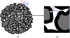 |
Fig. 3 Schematic representation of a pellet (a) and pores around constituting grains (b) showing the transport processes associated with the chemical reaction. |
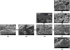 |
Fig. 4 SEM (Scanning Electron Microscope) micrographs showing the morphological changes at the granular scale in CVRD-DR pellets; (a) to (d): grains in different stages of a reduction at 800 °C; (d) to (g): iron grains after reduction at different temperatures; (h): polished cross-section at a conversion degree of 65% of a sample reduced at 900 °C, the red arrow points to shrinking wüstite cores (dark gray) surrounded with a spreading layer of iron (light gray), indicated by the blue arrow. All images by SE (secondary electrons), except (h) BSE (backscattered electrons). Reducing gas used: 2 L/min H2–He (60–40 vol.%) in a thermobalance. |
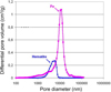 |
Fig. 5 Pore size distribution of a CVRD-DR pellet before and after reduction by H2 at 1000 °C. |
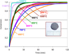 |
Fig. 6 Effect of temperature on the kinetics of reduction of one CVRD pellet under H2 (40%H2 in He), measured by thermogravimetry. |
3 Kinetic model of a single pellet
The modeling of reactors such as shaft furnaces requires a predictive calculation of the rate of the reduction reactions at any temperature and for any gas composition. For this purpose, we have designed a specific model, the kinetic model of a single pellet, which reproduces the observations and results obtained in the laboratory and which can be easily integrated into a multiparticle reactor model. Its principle is based on a geometrical representation of a spherical pellet made up of smaller grains (Fig. 8). Initially the grains are dense hematite. The inter- and intra-granular porosity evolves during the reduction. At the wüstite stage, the grains subdivide into crystallites. At the grain scale, the reactions are topochemical, with a shrinking core.
It is thus a more sophisticated model than the shrinking core pellet models, with one or three interfaces, often used in the literature. It should be noted here that experimentally, we do not observe concentric interfaces separating the different oxides and the iron at the pellet scale. The kinetic parameters used are taken from our own experiments (porosity measurements, specific surface) and from model-experiment fitting for the rate constants [19]. From a mathematical point of view, the model remains simple because it is based on the law of additive characteristic times [20]. This law, approximate but validated by several studies, allows us an analytical calculation of the reaction rate, even for mixed regimes. This single pellet model adapted to the reduction of iron ore by H2 and/or CO is described in more detail in [13,18,19,21].
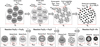 |
Fig. 8 Representation of the pellet (top row) and grain (bottom row) evolution in the single pellet kinetic model [11]. |
4 Multiparticle model of the shaft furnace
The shaft furnace for the reduction of iron ore with pure H2 is the core of the new process. In a conventional shaft furnace, the iron ore, in the form of pellets or lump ore, slowly descends by gravity into a vertical cylindrical shaft and is reduced by a CO–H2 mixture flowing upwards countercurrently. This bustle gas is introduced through the sidewall at mid-height and goes out at the top. In the MIDREX process (Fig. 9), the top gas is recycled to feed the burners and the reformer, in combination with natural gas. In the HYL process, the gas loop is somewhat different, the reformer may not exist. The bottom part of the shaft furnace is a cone, in which the DRI is cooled by a looping counterflow of natural gas.
To predict whether a similar shaft furnace could be operated under pure hydrogen, a powerful and economical means of evaluation is mathematical modeling. Several models of DR shaft furnaces have been published, which differ according to the description of the reactor (1D or 2D, with or without intermediate and cooling zones), the chemical reactions taken into account and the associated kinetic models, the description of the gas and solid flows, the numerical method of resolution. The most detailed models [21–24] give access to very interesting characteristics of the internal behavior of shaft furnaces. With the exception of REDUCTOR, presented below, none of them has been used so far to predict the operation of a shaft furnace under pure H2.
The REDUCTOR model simulates the operation of a MIDREX or HYL-ENERGIRON shaft furnace. A cylindrical upper part, a conical lower part and an intermediate cylindrical part are considered. The input data for the calculation are the flow rates, compositions and temperatures of the incoming streams (solid at the top, reducing gas at the side, and cooling gas at the bottom). The same output quantities (DRI at the bottom and gas at the top) are results of the calculation. Four scales are considered: reactor, porous moving bed, pellets and grains (Fig. 10). The main equations solved are material balances on solid species (Fe2O3, Fe3O4, FeO, Fe, C, gangue), gaseous species (H2, CO, H2O, CO2, CH4, N2), heat balances on gas and solid, momentum balances. The kinetic model of a single pellet is included as a subroutine of the reactor code.
The equations and the numerical method have already been presented [11,13,21] and will not be repeated here. Two MIDREX direct reduction furnaces of different sizes were simulated by REDUCTOR and the comparison of the calculated results with measurements was used to validate the model [18,21].
Below we present the results of the simulation of a furnace that would operate under pure H2, without CO and CH4, limited to the reduction zone. The height is 6 m, the diameter 6.6 m. The solid charge consists of hematite pellets, its flow rate is 52 kg s−1. The gas (98%H2, 2%H2O) enters at 800 °C with a flow rate of 3634 mol s−1 from the side and 100 mol s−1 from the bottom.
The map of the mass fractions of the solids (Fig. 11) reveals that the reduction of hematite to magnetite is very fast, followed by the reduction of magnetite to wüstite, then the reduction of wüstite to iron is the slowest. It is however entirely completed at 3 m below the solid inlet, whereas the whole height is necessary for a metallization of about 95% in a conventional MIDREX furnace operating under CO–H2.
The temperature map (Fig. 12) shows that gas and solids are almost at the same temperature everywhere, except at the very top where the solid goes very quickly from 25 to 600 °C. Slight radial and especially axial thermal gradients are noted in the upper half of the furnace due to the endothermicity of the reduction. The map of H2 and H2O molar fractions (Fig. 13) illustrates the progressive consumption of H2 and the corresponding production of H2O (from z = 3 m to z = 6 m) corresponding to the reduction of oxides to iron. Not all H2 is used, far from it, since 72% of H2 remains in the top gas. This is not due to a poor utilization of H2 but to the fact that a flow rate much higher (3.8 times) than the stoichiometric flow rate necessary for the reduction must be circulated in order to heat the furnace.
Figure 14 shows the effect of the reduction gas temperature on the iron mass fraction. The case at 800 °C has already been presented. At higher temperatures, a complete reduction is obtained faster. Between 900 and 950 °C, the difference is little because of the kinetic slowdown mentioned. Moreover, above 900 °C, the gain seems small compared to the need to spend more energy. At 700 °C, the temperature is not sufficient to heat the furnace and iron appears only very partially, near the injection point.
These simulations need to be complemented by other ones, and confronted with experiments or other recent modeling results [25,26]. They do not answer all the questions related to the use of pure H2. However, they clearly show that a complete reduction of iron ore pellets by H2 in a shaft furnace is quite feasible.
 |
Fig. 11 Calculated solid mass fractions in a shaft furnace fed with H2 at 800 °C. The symmetry axis is on the left-hand side of each map, and the wall is on the right-hand side. The main gas inlet is at the wall near the bottom of the reactor. |
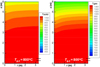 |
Fig. 12 Calculated temperatures (K) in a shaft furnace fed with H2 at 800 °C. |
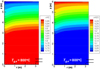 |
Fig. 13 Calculated molar gas fractions in a shaft furnace fed with H2 at 800 °C. |
 |
Fig. 14 Effect of the bustle gas temperature (Tg,e: 700 to 1100 °C) on the iron mass fraction in a shaft furnace fed with H2. |
5 Conclusion
In the context of the fight against global warming, the need to drastically reduce CO2 emissions in the industrial sectors most concerned has recently led the steel industry to seriously consider the hydrogen option. The most promising hydrogen-based steelmaking route is the direct reduction of iron ore by pure H2 followed by electric steelmaking. It indeed combines a certain technological maturity and very good performance in terms of emissions reduction (more than 85% decrease). Hydrogen must be green or produced through low-carbon processes, and the solution that appears to be the most efficient to produce the large quantities needed is the electrolysis of water with decarbonized electricity (renewable or nuclear). Numerous projects in line with this new route are starting, focusing either on the development of large capacity electrolysers or, more rarely until now, on the demonstration of the viability of the direct reduction process with pure H2.
The research carried out on this topic at the Institut Jean Lamour, University of Lorraine, France, initiated during the ULCOS program and continued since, has provided a set of valuable results.
The experimental study of the reduction of ore pellets by H2 shows that the reaction is faster than with CO and that a complete metallization is obtained in the laboratory, even when a dense iron layer is formed around the wüstite grains. The influence of the temperature is complex, with the appearance of kinetic slowdowns at the end of the reaction at 700 and 950 °C. We have proposed a sophisticated single pellet kinetic model based on experimental observations and capable of simulating mixed kinetic regimes.
Dealing with the reactor scale, the use of the REDUCTOR model to simulate a shaft furnace operated under pure H2 has provided significant first results. It seems possible to obtain a complete metallization under H2 and to use a squatter furnace than the current direct reduction furnaces. Temperatures between 800 and 950 °C seems adequate. However, these simulations should be extended to the case of a complete furnace, including the lower conical zone. The model can be used to guide towards optimal dimensions and operating conditions.
The points that we believe deserve further investigations are: some very scientific questions on kinetic slowdowns, occurrence of sticking, solid flow, more technological questions such as the design and optimal operating conditions of a H2 shaft furnace and its gas loop, the consequences of using carbon-free DRI in the electric furnace, the materials best suited to H2–H2O atmospheres, more industrial questions such as the integration of a direct reduction unit in a conventional integrated plant, with its consequences on the valorization of the coke oven, BF and BOF gases and on the best use of the DRI.
References
- WorldSteel Association, Steel Statistical Yearbook 2020, 2020 https://www.worldsteel.org/steel-by-topic/statistics/steel-statistical-yearbook.html (accessed on 25/10/2021) [Google Scholar]
- L. Holappa, A general vision for reduction of energy consumption and CO2 emissions from the steel industry, Metals 10, 1117 (2020) [CrossRef] [Google Scholar]
- J.-P. Birat, M. Antoine, A. Dubs, et al., Vers une sidérurgie sans carbone ?, in: Journées sidérurgiques 1992, 16 au 17 décembre, 1992 and Revue de métallurgie 90, 411 (1993) [Google Scholar]
- CIRCORED Hydrogen-based reduction, METSO-OTTOTEC, https://www.mogroup.com/portfolio/circored-hydro-gen-based-reduction [Google Scholar]
- J.-P. Birat, J. Borlée, B. Korthas, et al., ULCOS program: A progress report in the spring of 2008, in: Scanmet III, 3rd International Conference on Process Development in Iron and Steelmaking, 8–11 June, 2008, Lulea, Sweden [Google Scholar]
- J.-P. Birat, CO2-lean steelmaking: ULCOS, other international programs and emerging concepts, in: ECCR Steel (METEC- 2011), 2011 [Google Scholar]
- J.-P. Birat, The progress and status of IISI’s CO2 Breakthrough Program and EU’s ULCOS, in: CO2 Reduction Workshop, Kaohsiung, Taiwan, 1–2 November, 2007 [Google Scholar]
- Breaking through the technology barriers: Steel producers are researching new production technologies that would radically reduce their environmental footprint, FACT SHEET – Breakthrough technologies, Worldsteel pamphlet, 10/ 2008 [Google Scholar]
- J.-P. Birat, F. Patisson, O. Mirgaux, Hydrogen Steelmaking, part 2: Competition with other zero-carbon steelmaking solutions – geopolitical issues, Matériaux & Techniques, (2021), in press [Google Scholar]
- M. Hutson, The promise of carbon-neutral steel, The New Yorker, Sept. 18, 2021, https://www.newyorker.com/news/annals-of-a-warming-planet/the-promise-of-carbon-neutral-steel (accessed on 26 October 2020) [Google Scholar]
- F. Patisson, O. Mirgaux, Hydrogen ironmaking: How it works, Metals 10, 922 (2020) [CrossRef] [Google Scholar]
- Hybrit (Hydrogen Breakthrough Ironmaking Technology) brochure, Available from https://ssabwebsitecdn.azureedge.net/-/media/hybrit/files/hybrit_brochure.pdf (accessed on 26/11/2020) [Google Scholar]
- A. Ranzani da Costa, D. Wagner, F. Patisson, Modelling a new, low CO2 emissions, hydrogen steelmaking process, J. Clean. Prod. 46, 27–35 (2013) [CrossRef] [Google Scholar]
- N. Towhidi, J. Szekely, Reduction kinetics of commercial low-silica hematite pellets with CO-H2 mixtures over temperatures range 600-1234 °C, Ironmak Steelmak. 6, 237–249 (1981) [Google Scholar]
- A. Bonalde, A. Henriquez, M. Manrique, Kinetic analysis of the iron oxide reduction using hydrogen-carbon monoxide mixtures as reducing agent, ISIJ Int. 45(9), 155–1260 (2005). [Google Scholar]
- MIDREX, https://www.midrex.com/technology/midrex-process/ (accessed on 26/10/2020) [Google Scholar]
- HYL-ENERGIRON, https://www.tenova.com/product/iron-reduction-technologies/ (accessed on 26/10/2020) [Google Scholar]
- H. Hamadeh, Modélisation mathématique détaillée du procédé de réduction directe du minerai de fer, Ph.D. Thesis, Université de Lorraine, Nancy, France, 2017, Available from https://tel.archives-ouvertes.fr/tel-01740462 [Google Scholar]
- A. Ranzani da Costa, La réduction du minerai de fer par l’hydrogène : étude cinétique, phénomène de collage et modélisation, Ph.D. Thesis, Institut national polytechnique de Lorraine, Nancy, France, 2011, Available from https://tel.archives-ouvertes.fr/tel-01204934/ [Google Scholar]
- H.Y. Sohn, The law of additive reaction times in fluid-solid reactions, Metall. Trans. 9B, 89–96 (1978) [CrossRef] [Google Scholar]
- H. Hamadeh, O. Mirgaux, F. Patisson, Detailed modeling of the direct reduction of iron ore in a shaft furnace, Materials 11, 1865 (2018) [CrossRef] [Google Scholar]
- D.R. Parisi, M.A. Laborde, Modeling of counter current moving bed gas-solid reactor used in direct reduction of iron ore, Chem. Eng. J. 104, 35–43 (2004) [CrossRef] [Google Scholar]
- M.S. Valipour, Y. Saboohi, Numerical investigation of nonisothermal reduction of haematite using syngas: The shaft scale study, Model. Simul. Mater. Sci. Eng. 15, 487–507 (2007) [CrossRef] [Google Scholar]
- A. Shams, F. Moazeni, Modeling and simulation of the MIDREX shaft furnace: reduction, transition and cooling zones, JOM 67, 2681–2689 (2015) [CrossRef] [Google Scholar]
- K. Rechberger, et al., Green hydrogen-based direct reduction for low-carbon steelmaking, Steel Res. Int. 91, 2000110 (2020) [CrossRef] [Google Scholar]
- L. Shao et al., Computational analysis of hydrogen reduction of iron oxide pellets in a shaft furnace process, Renew. Energy 179, 1537–1547 (2021) [CrossRef] [Google Scholar]
Cite this article as: Fabrice Patisson, Olivier Mirgaux, Jean-Pierre Birat, Hydrogen steelmaking. Part 1: Physical chemistry and process metallurgy, Matériaux & Techniques 109, 303 (2021)
All Tables
All Figures
 |
Fig. 1 ULCOS hydrogen-based route to steel [11]. |
| In the text | |
|
Fig. 2 Phase diagram of the iron phase domains as a function of the oxidizing power of the gas and temperature, for the gas mixtures CO–CO2 and H2–H2O. The arrows represent the driving force for the wüstite-to-iron reduction. |
| In the text | |
|
Fig. 3 Schematic representation of a pellet (a) and pores around constituting grains (b) showing the transport processes associated with the chemical reaction. |
| In the text | |
|
Fig. 4 SEM (Scanning Electron Microscope) micrographs showing the morphological changes at the granular scale in CVRD-DR pellets; (a) to (d): grains in different stages of a reduction at 800 °C; (d) to (g): iron grains after reduction at different temperatures; (h): polished cross-section at a conversion degree of 65% of a sample reduced at 900 °C, the red arrow points to shrinking wüstite cores (dark gray) surrounded with a spreading layer of iron (light gray), indicated by the blue arrow. All images by SE (secondary electrons), except (h) BSE (backscattered electrons). Reducing gas used: 2 L/min H2–He (60–40 vol.%) in a thermobalance. |
| In the text | |
|
Fig. 5 Pore size distribution of a CVRD-DR pellet before and after reduction by H2 at 1000 °C. |
| In the text | |
|
Fig. 6 Effect of temperature on the kinetics of reduction of one CVRD pellet under H2 (40%H2 in He), measured by thermogravimetry. |
| In the text | |
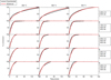 |
Fig. 7 Reduction of CVRD pellets under CO–H2 mixtures in a thermobalance [18]. |
| In the text | |
|
Fig. 8 Representation of the pellet (top row) and grain (bottom row) evolution in the single pellet kinetic model [11]. |
| In the text | |
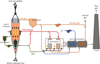 |
Fig. 9 Schematic diagram of the direct reduction process [21]. |
| In the text | |
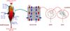 |
Fig. 10 The four scales in the REDUCTOR model [21]. |
| In the text | |
|
Fig. 11 Calculated solid mass fractions in a shaft furnace fed with H2 at 800 °C. The symmetry axis is on the left-hand side of each map, and the wall is on the right-hand side. The main gas inlet is at the wall near the bottom of the reactor. |
| In the text | |
|
Fig. 12 Calculated temperatures (K) in a shaft furnace fed with H2 at 800 °C. |
| In the text | |
|
Fig. 13 Calculated molar gas fractions in a shaft furnace fed with H2 at 800 °C. |
| In the text | |
|
Fig. 14 Effect of the bustle gas temperature (Tg,e: 700 to 1100 °C) on the iron mass fraction in a shaft furnace fed with H2. |
| In the text | |
Current usage metrics show cumulative count of Article Views (full-text article views including HTML views, PDF and ePub downloads, according to the available data) and Abstracts Views on Vision4Press platform.
Data correspond to usage on the plateform after 2015. The current usage metrics is available 48-96 hours after online publication and is updated daily on week days.
Initial download of the metrics may take a while.